Image processing method, image processing apparatus, and program

a technology of image processing and image data, applied in the field of image processing technology, can solve the problems of deterioration of image quality, decreased processing speed and extraction of excessive dividing points, and low approximation precision, and achieve the effect of high precision

Inactive Publication Date: 2012-03-01
CANON KK
View PDF2 Cites 16 Cited by
  • Summary
  • Abstract
  • Description
  • Claims
  • Application Information

AI Technical Summary

Benefits of technology

[0016]The present invention has been conceived in view of the above problems, and allows curve approximation processing with high precision to be performed in a simple manner.
[0020]Approximation processing can be performed in a simple manner without using feedback.
[0021]Excessive extraction of a dividing point can be prevented, and the amount of data can be reduced.
[0022]Thus, compared with conventional technology, approximation processing with higher precision can be performed in a simpler way.

Problems solved by technology

Even if the image whose size has been changed in this way is output using a high resolution device, the deterioration of image quality will be noticeable since it is not possible to take advantage of the resolution of the image.
However, a method for deciding a tangential direction is not specified in Japanese Patent Laid-Open No. 2005-310070.
Further, a result of the approximation is fed back, and if it is determined that the precision is low, a dividing point is added, which may cause a decrease in the processing speed and extraction of an excessive dividing point.
However, in Japanese Patent Laid-Open No. 04-116690, the direction of an adjacent coordinate point is uniquely decided as the tangential direction, and the approximation precision may not be high if noise is included in an approximation section.
However, in Japanese Patent Laid-Open No. 04-287173, least square approximation is necessary as preprocessing of Bezier approximation processing, which may cause a decrease in the processing speed.
As described above, with the conventional vectorization method, the approximation precision with respect to raster data serving as the basis of vector data that has been obtained and the load of vectorization processing are in a trade-off relationship with each other, and thus it has been difficult to obtain vector data with high precision by simple processing.

Method used


Image

  • Image processing method, image processing apparatus, and program
  • Image processing method, image processing apparatus, and program
  • Image processing method, image processing apparatus, and program

Examples


embodiment 1

[0045]Below is a description of embodiments of the present invention with reference to the attached drawings. However, it should be noted that the constituent elements described in the embodiments are to be taken as examples only, and the technical scope of the present invention is defined by the appended claims, and is not intended to be limited by the individual embodiments described below.

[0046]Example of Configuration of Image Processing Apparatus

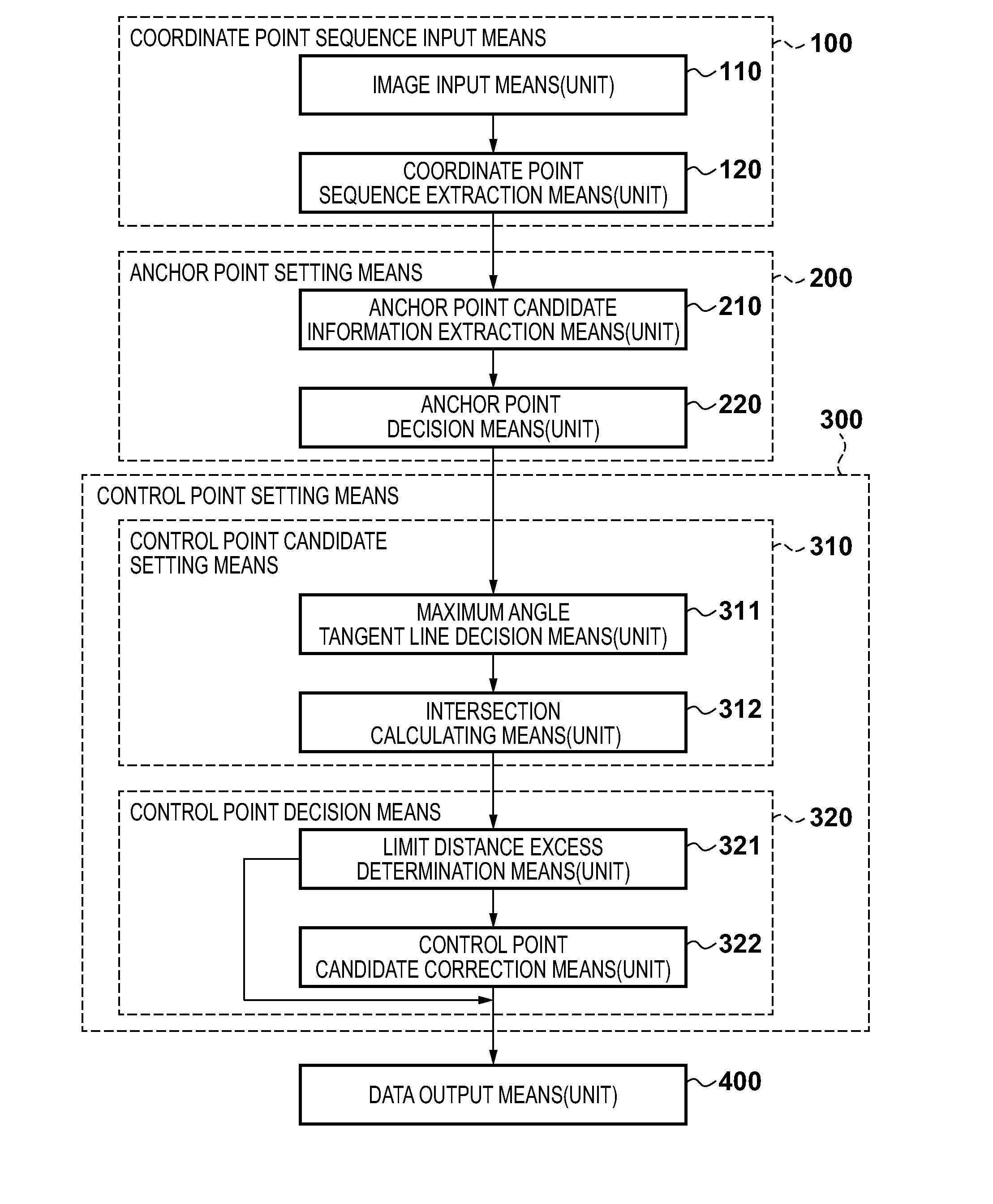
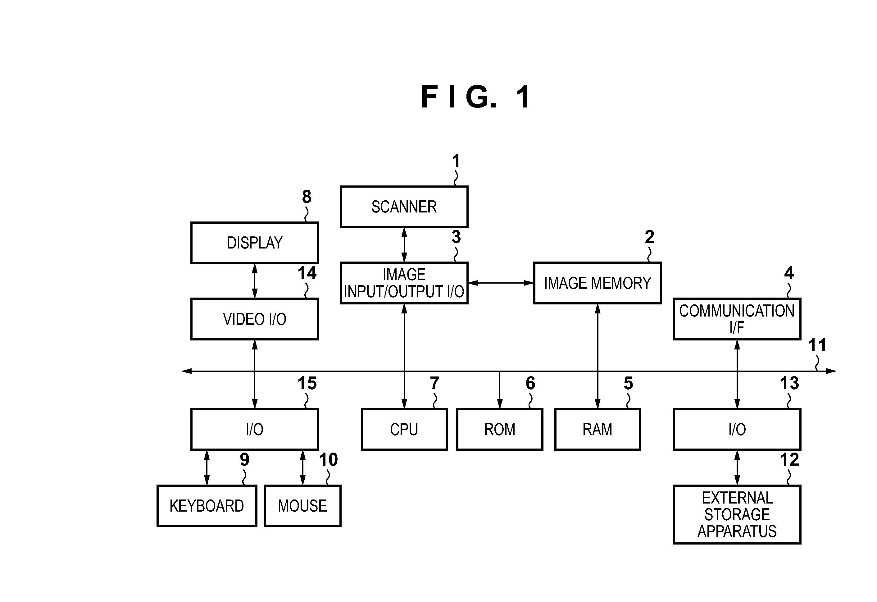
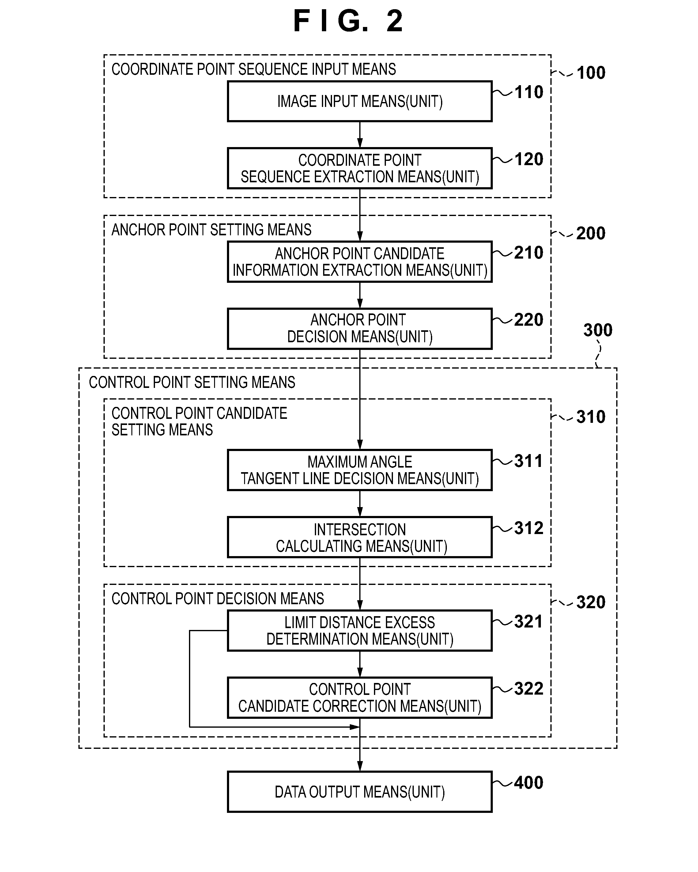
[0047]An example of a configuration of an image processing apparatus according to the present embodiment will be described with reference to the block diagram in FIG. 1. The image processing apparatus may be achieved by a general purpose computer or a peripheral apparatus such as a multifunctional copying machine (MFP). In FIG. 1, a CPU 7 is a processing unit that performs overall control of the apparatus. The procedure of a flowchart described in the present embodiment is realized by the CPU 7 executing a program that describes this pr...

embodiment 2

[0107]In Embodiment 1, in anchor point decision processing, elimination processing is performed if another anchor point candidate exists within two coordinate points before and after an anchor point candidate of interest. However, in a case in which coordinate points included between anchor point candidates are separated by three points or more, even if a redundant anchor point candidate exists, such a point cannot be eliminated. According to the present embodiment, if a sequence is partitioned into a unit approximation section in a range that can be represented by a quadratic curve, it is possible to perform approximation processing without failure, and thus further anchor point candidate elimination may be performed.

[0108]In view of this, in the present embodiment, the priorities of adjacent anchor point candidates are compared, and then elimination processing is performed. Further, if elimination is performed by comparing anchor point candidates, the result of the elimination is ...

embodiment 3

[0115]In Embodiment 1, in anchor point candidate extraction processing, anchor point candidate information is extracted by tracking the coordinate point sequence extracted in step S120. At this time, it is necessary to calculate the angle of a coordinate point sequence for attributes such as “inflection point” and “critical point” according to which extraction is performed using a change in angle, and thus as shown in FIG. 18A, determination is performed on every other point.

[0116]However, at this time, even in a case of the same coordinate point sequences, different extraction results will be obtained in a case in which a coordinate point sequence 1 in FIG. 18A is determined and a case in which a coordinate point sequence 2 in FIG. 18A is determined, and thus the final approximation results may not match in the two cases.

[0117]In order to handle this, in anchor point candidate information extraction processing in Embodiment 1, “inflection point” and “critical point” determination i...


PUM


Abstract

Function approximation performed when a raster image is converted into a vector image is performed in a simple manner with high accuracy, without using feedback. When anchor points are extracted from a coordinate point sequence obtained from the raster image, and function approximation is performed on the coordinate point sequence between anchor points, an appropriate point among coordinate points defined in a unit approximation section that is partitioned by anchor points is selected, and after setting the direction of the corresponding coordinate point as a tangential direction, correction is performed such that the position of a control point obtained from a tangent line does not intersect another control point.

Description

BACKGROUND OF THE INVENTION[0001]1. Field of the Invention[0002]The present invention relates to image processing technology, and in particular to an image processing apparatus that converts a raster image into a vector image by extracting feature points from the raster image and performing function approximation, an image processing method, and a program.[0003]2. Description of the Related Art[0004]In recent years, devices with different resolutions such as a display and a printing device are used in combination, and the opportunity to display one image information piece at different resolutions is increasing. If an image suitable for a low resolution device is to be displayed or printed using a high resolution device, the output size will be small as is, and thus it is necessary to convert the image so as to have an original size by interpolating pixels, for instance. Even if the image whose size has been changed in this way is output using a high resolution device, the deteriorat...

Claims


Application Information

Patent Timeline
Patent Type & Authority Applications(United States)
IPC IPC(8): G06K9/48
CPCG06T9/001G06K9/481G06V10/469
Inventor OTO, HIROSHI
Owner CANON KK
Why Eureka
Try Eureka