
Retaining ring arrangement for a rotary assembly

a technology of retaining ring and rotary assembly, which is applied in the direction of liquid fuel engine, vessel construction, marine propulsion, etc., can solve the problems of premature wear of the ring, jeopardizing the integrity of the assembly, etc., and achieve the effect of preventing disengagemen

Active Publication Date: 2012-03-01
PRATT & WHITNEY CANADA CORP
View PDF3 Cites 35 Cited by
  • Summary
  • Abstract
  • Description
  • Claims
  • Application Information

AI Technical Summary

Benefits of technology

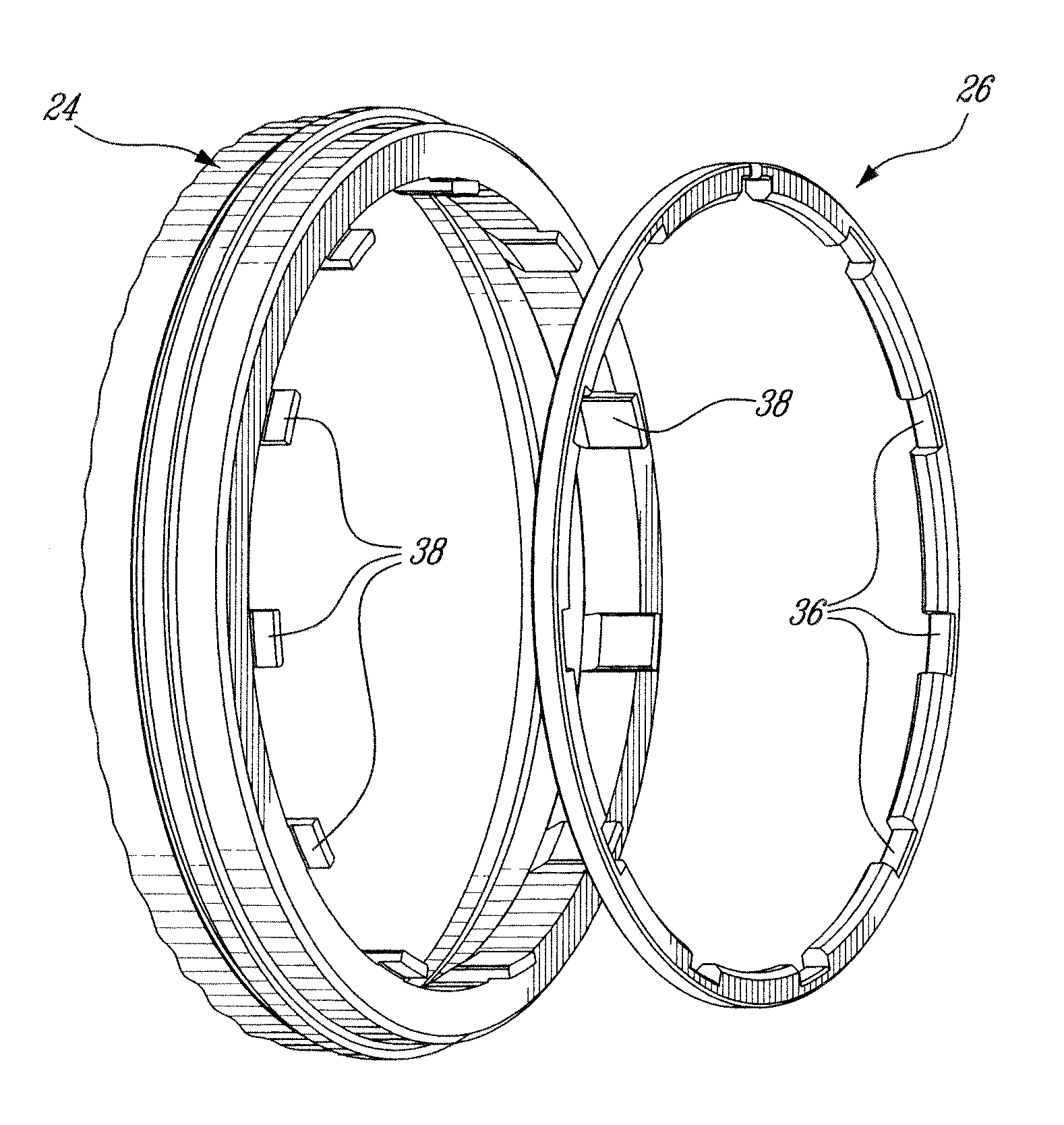
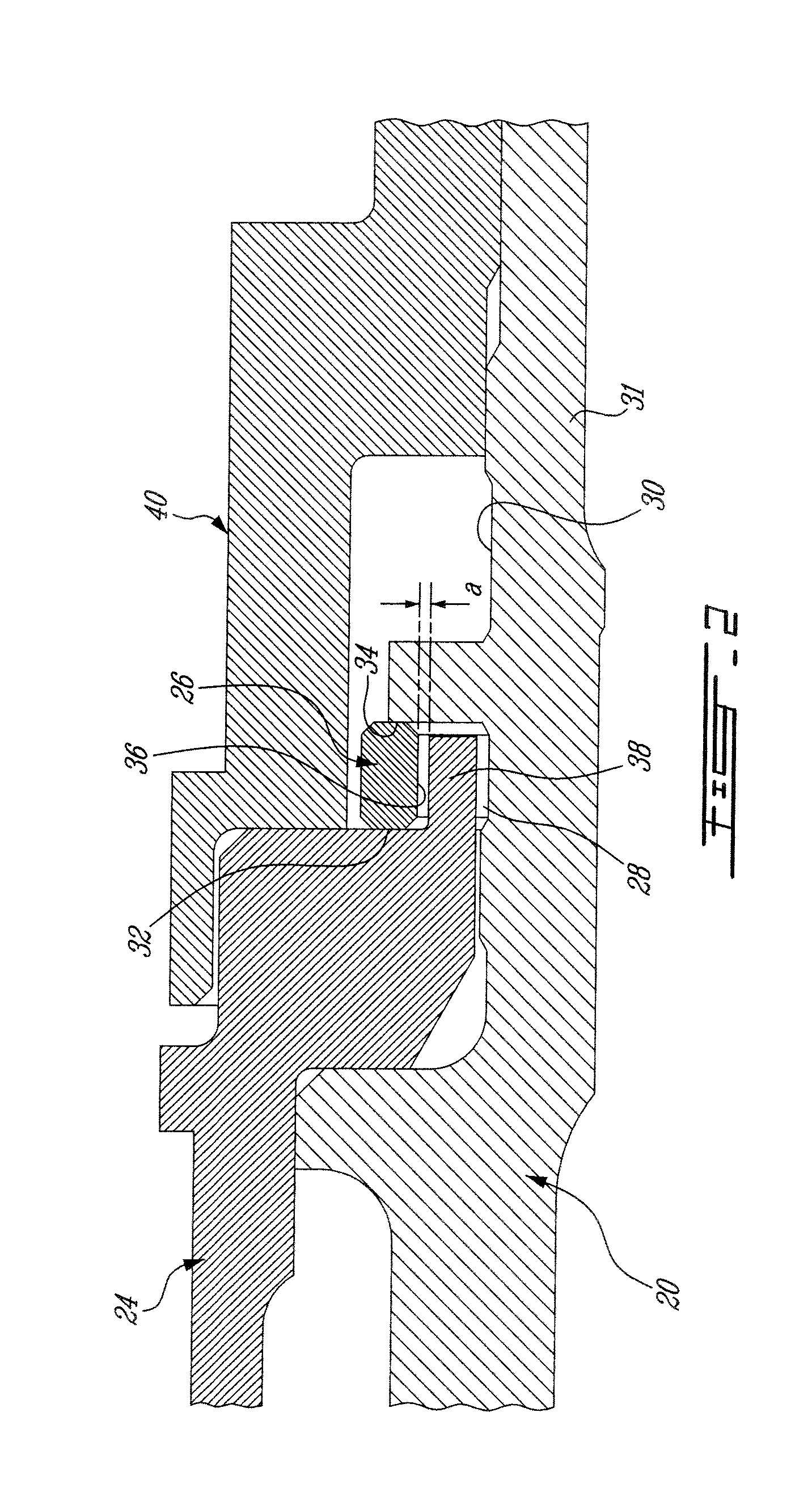
[0004]In one aspect, there is provided a gas turbine engine rotary assembly comprising: a first component mounted for rotation about an axis of the gas turbine engine, a second component mounted on said first component, a retaining ring received in a circumferential groove defined in a radially outer surface of the first component, the retaining ring providing an axially facing shoulder for axially retaining the second component onto the first component, the retaining ring having at an inner diameter thereof a radially inner surface defining a plurality of circumferentially spaced-apart grooves for engagement with at least one anti-rotation lug projecting from one of said first and second components, thereby restraining the retaining ring against rotation relative to said one of the first and second components. the retaining ring having a split ring body which is spring-loaded radially inwardly at said inner diameter against a circumferential seat provided on a radially outer surface of one of said first and second components, and an outer sleeve surrounding the split ring body to limit radial expansion of the split ring body and thereby prevent disengagement of the anti-rotation lug from the split ring body as a result of centrifugal forces transferred to the retaining ring during gas turbine engine operation.

Problems solved by technology

If the ring is not flexible enough, the ring may plastically deformed and, thus, jeopardize the integrity of the assembly.
In use, rotation of the retaining ring in the inside diameter groove may cause premature wear of the ring.

Method used


Image

  • Retaining ring arrangement for a rotary assembly
  • Retaining ring arrangement for a rotary assembly
  • Retaining ring arrangement for a rotary assembly

Examples


Embodiment Construction

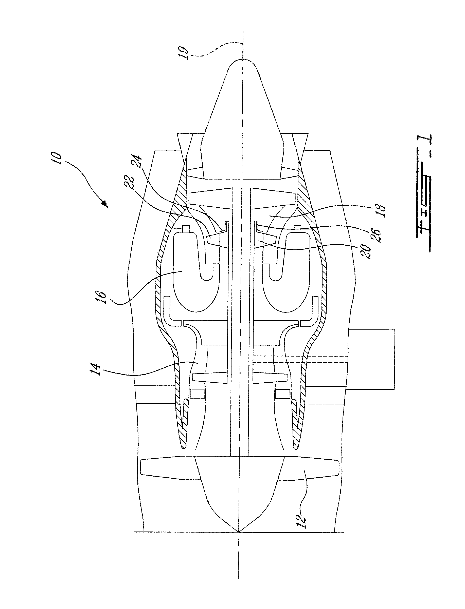
[0013]FIG. 1 illustrates a turbofan gas turbine engine 10 of a type preferably provided for use in subsonic flight, generally comprising in serial flow communication a fan 12 through which ambient air is propelled, a multistage compressor 14 for pressurizing the air, a combustor 16 in which the compressed air is mixed with fuel and ignited for generating an annular stream of hot combustion gases, and a turbine section 18 for extracting energy from the combustion gases.

[0014]As schematically illustrated in FIG. 1, the turbine section 18 comprises a turbine disc 20 mounted for rotation about the engine centerline 19. The turbine disc 20 carries a circumferential array of turbine blades 22 which extend into the gaspath downstream of the combustor 16. A coverplate 24 covers the aft face of the turbine disc 20. A retaining ring 26 is used to axially retain the coverplate 24 on the turbine disc 20.

[0015]As shown in FIG. 2, the retaining ring 26 is mounted in a circumferential groove 28 de...


PUM


Abstract

A retaining ring arrangement is provided for axially holding a component on a rotating component of a gas turbine engine. The retaining ring arrangement comprises a split retaining ring mounted in a circumferential groove defined in a radially outer surface of the rotating component. The inner diameter of the retaining ring is biased inwardly in radial contact with a radially outer facing seat provided on one of the two components to be assembled. An anti-rotation feature is provided at the inner diameter of the retaining ring for restraining the ring against rotation. A sleeve surrounds the retaining ring to limit radial expansion thereof when subject to centrifugal forces during engine operation.

Description

TECHNICAL FIELD[0001]The application relates generally to a gas turbine engine rotary assembly and, more particularly, to a retaining ring arrangement for axially retaining a first component on a second rotary component.BACKGROUND OF THE ART[0002]Retaining rings used in turbine assemblies are generally loaded radially outwardly in an inside diameter groove. The ring has to be collapsed in to allow the assembly of the part to be retained. If the ring is not flexible enough, the ring may plastically deformed and, thus, jeopardize the integrity of the assembly. In use, rotation of the retaining ring in the inside diameter groove may cause premature wear of the ring.[0003]There is thus a need for a new retaining ring arrangement providing flexibility and safety in the handling and transportation of a rotary assembly during manufacture and overhaul.SUMMARY[0004]In one aspect, there is provided a gas turbine engine rotary assembly comprising: a first component mounted for rotation about a...

Claims


Application Information

Patent Timeline
IPC IPC(8): F01D5/02
CPCF01D5/025F05D2300/501F05D2260/36F01D5/026
Inventor GLASSPOOLE, DAVID F.CHATELOIS, BRUNO
Owner PRATT & WHITNEY CANADA CORP
Learn More