Supercharge Your Innovation With Domain-Expert AI Agents!

Network Relay Device and Frame Relaying Control Method

a network relay and control method technology, applied in the field of network relay devices, can solve the problems of sacrificing the other, increasing the burden of network administrators in managing network configuration, and common security problems of network relay devices with security functions, and achieve the effect of improving security and convenien

Inactive Publication Date: 2012-03-01
BUFFALO CORP LTD
View PDF8 Cites 11 Cited by
  • Summary
  • Abstract
  • Description
  • Claims
  • Application Information

AI Technical Summary

Benefits of technology

The present invention is a network relay device that can relay data frames received from external devices. The device has multiple ports that are pre-correlated with different types of authentication to be conducted with connected external devices. The device includes an authentication process section that determines the type of authentication and conducts mutual authentication with the external device using an authentication protocol chosen based on the type of connected external device. The device also has a relay process section that relays frames received from the external device. The device can also stop relaying frames and conduct a key-exchange process if requested. The device includes a permission list that changes content based on the external device's state of connection. The invention allows for flexible dealing with changes in network configuration while ensuring security in the network relay device. It is applicable to network systems and wireless communications.

Problems solved by technology

Meanwhile, there is a trade-off relationship between convenience and strengthening security, and the fact of the matter is pursuing one leads to sacrificing the other.
Consequently, network administrators have to deal with changes in the network configuration while ensuring security, such that a problem for network administrators has been an increased burden in managing network configurations.
What is more, this sort of problem has not been limited to intelligent switches, but on the whole has been a problem common to network relay devices with security functions.

Method used


Image

  • Network Relay Device and Frame Relaying Control Method
  • Network Relay Device and Frame Relaying Control Method
  • Network Relay Device and Frame Relaying Control Method

Examples


first embodiment

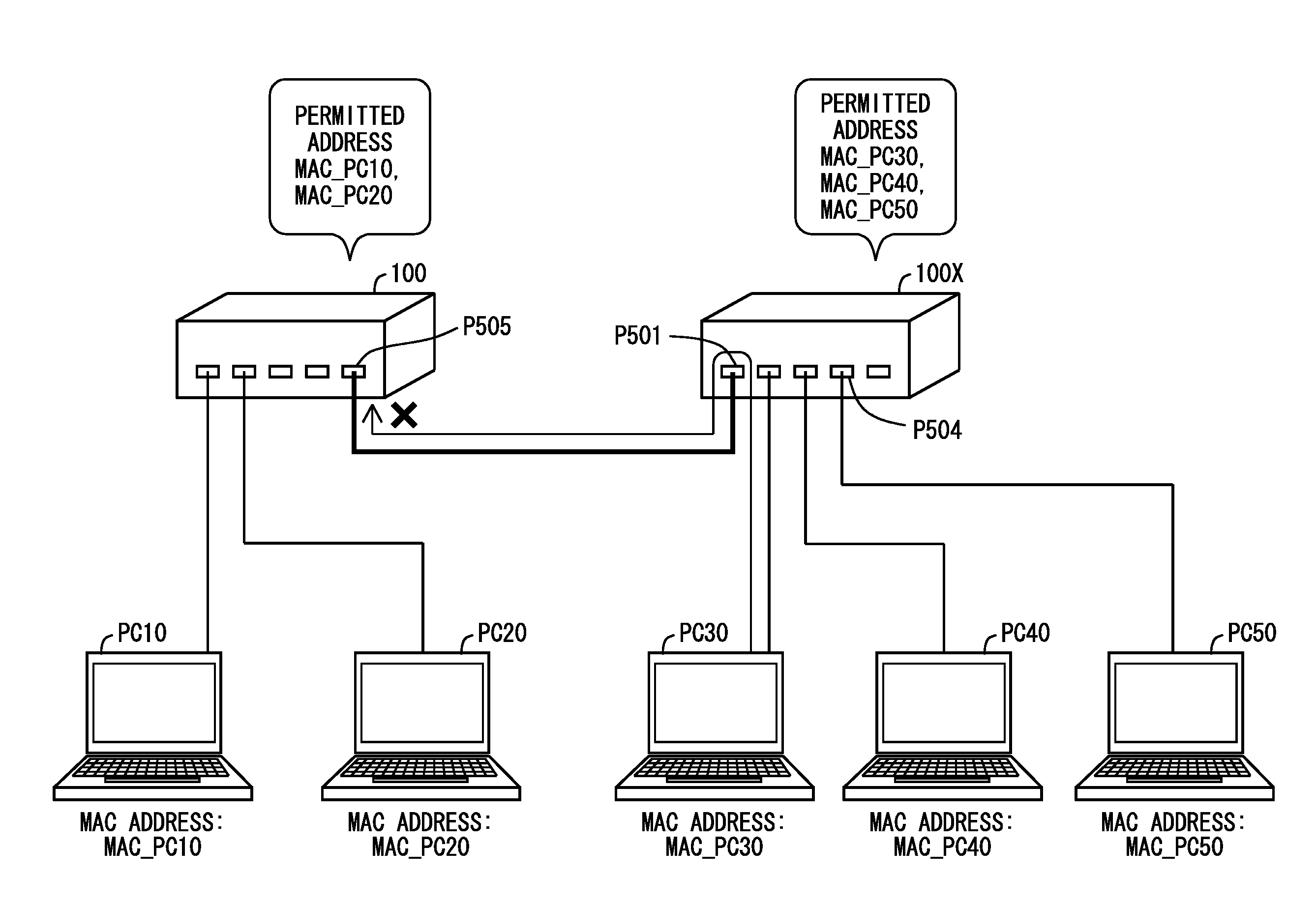
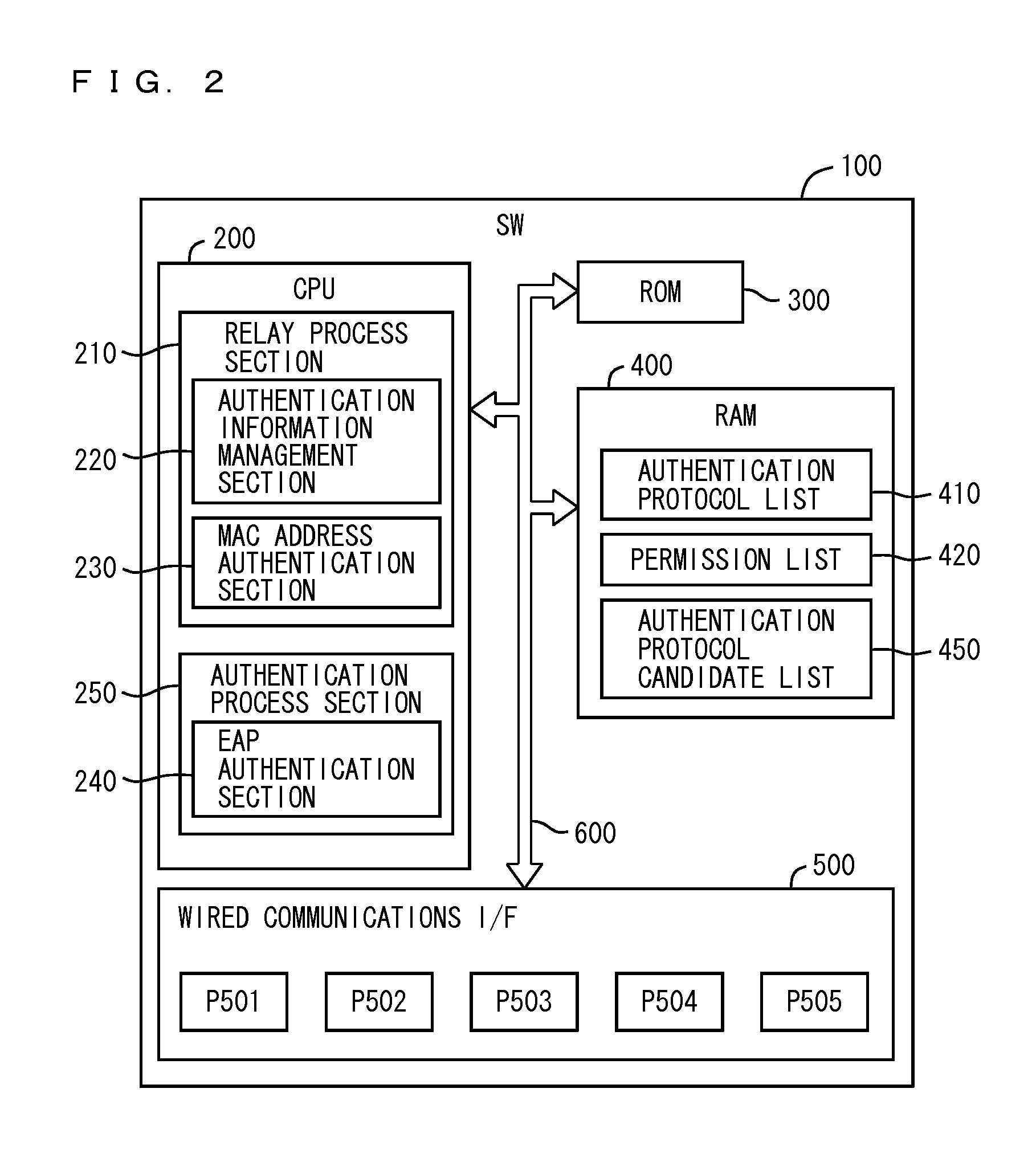
[0035]FIG. 1 is a diagram showing a schematic configuration of a terminal PC10, a terminal PC20, and a network relay device 100 according to a first embodiment of the present invention. The network relay device 100 according to the first embodiment is a so-called layer 2 switch, and functions to relay a frame by using a MAC (Media Access Control) address. Layer 2 corresponds to the second layer (data link layer) of the OSI (Open Systems Interconnection) reference model. In the following, descriptions are provided by representing the network relay device 100 as a switch 100. An external device (e.g., a terminal or another switch) is connected to the switch 100 via five ports, P501 to P505.

[0036]In the example shown in FIG. 1, the terminal PC10, which is a personal computer or the like, is connected to the port P501 via a line. The MAC address of the terminal PC10 is MAC_PC10. The terminal PC20, which is a personal computer or the like, is connected to the port P502 via a line. The MA...

second embodiment

[0092]Described in a second embodiment of the present invention is a configuration further including a process of exchanging keys used for authentication in the network relay device (switch) 100 of the first embodiment. In the following, descriptions of the second embodiment are provided only for those having a configuration or operation that is different from the first embodiment. It should be noted that, in the figures used for the second embodiment, components identical to those in the first embodiment are given reference characters identical to those in the first embodiment, and detailed descriptions of those are omitted.

[0093]FIG. 13 is a diagram schematically representing a configuration of a network relay device (switch) 100a according to the second embodiment of the present invention. The switch 100a according to the second embodiment differs from the switch 100 according to the first embodiment shown in FIG. 2 with regard to an EAP authentication section 240a including a ke...

modification 1

[0104]The configurations of the switches shown in each of the embodiment described above are merely examples and other configurations may be adopted. For example, as described in the following, modifications such as an omission of a part of the components and a further addition of components can be devised.

[0105]Instead of using layer 2 switches to relay frames by using MAC addresses, the switches in each of the embodiments may be layer 3 switches that are further capable of relaying packets by using IP addresses. Furthermore, the switches in each of the embodiments may be so-called access points capable of relaying packets of wireless communication via wireless-communication interfaces.

[0106]Furthermore, the switches of each of the above described embodiments may further include, for example, a VLAN function for building virtual subnetworks, a link aggregation function for logically combining a plurality of ports to be handled as a one, and the like.

[0107]Furthermore, although the ...


PUM


Abstract

A network relay device includes: a plurality of ports to which external devices connect, and configured pre-correlated with types of authentication to be conducted with respect to connected external devices; an authentication process section for determining, when an external device is connected to the network relay device, the type of authentication that the port to which the external device is connected is configured for, and if the determined type of authentication is a first authentication type, conducting mutual authentication between the network relay device and the external device using an authentication protocol chosen from among a plurality of authentication protocol candidates in accordance with type of connected external device; and a relay process section for relaying frames received from an external device with which authentication by the authentication process section has succeeded.

Description

CROSS REFERENCE TO RELATED APPLICATION[0001]The disclosure of Japanese Patent Application No. 2010-186831, filed on Aug. 24, 2010, is incorporated herein by reference.BACKGROUND OF THE INVENTION[0002]1. Field of the Invention[0003]The present invention relates to network relay devices and methods that the network relay devices execute for controlling relay of data frames received from external devices.[0004]2. Description of the Background Art[0005]Accompanying advances in information and communications technology (ICT), switching products known as intelligent switches have appeared. Such intelligent switches signify switching that is highly functional by comparison to general switches. Intelligent switches have a variety of functions including, for example, virtual local area network (VLAN) functions, security functions, and functions related to quality of service (QoS) (cf., for example, Japanese Laid-Open Patent Publication No. 2008-48252). Among the functions described above, im...

Claims


Application Information

Patent Timeline
Patent Type & Authority Applications(United States)
IPC IPC(8): G06F15/16H04L12/28H04L12/46H04L12/70
CPCH04L63/0869H04L63/162H04L63/101
Inventor YAMADA, DAISUKE
Owner BUFFALO CORP LTD
Features
  • R&D
  • Intellectual Property
  • Life Sciences
  • Materials
  • Tech Scout
  • Unparalleled Data Quality
  • Higher Quality Content
  • 60% Fewer Hallucinations
Learn More