Magnetic motor and automobile

a technology for automobiles and magnets, applied in the direction of motors/generators/converter stoppers, propulsion parts, etc., can solve the problems of wasting energy, reducing the range of these vehicles, and exceeding the high-pressure that has been necessary, so as to reduce the friction of shaft turning and ensure the effect of high rotational speed, safety and reliability

Inactive Publication Date: 2012-03-08
MAGNETIC AIR MOTORS
View PDF14 Cites 20 Cited by
  • Summary
  • Abstract
  • Description
  • Claims
  • Application Information

AI Technical Summary

Benefits of technology

[0019]Briefly, a magnetic motor and automobile embodiment of the present invention uses a magnetic motor and star rotor compressor to pack high-pressure input air into storage tanks. The compressor and storage tanks deliver the high-pressure working air and operational flows to several stages of compressors that boost the pressures during driving to very high-pressure, then ultra high-pressure, then super high-pressure, and finally to extremely high-pressure. A pneumatic torque converter uses jets of the extremely high-pressure to turn an input shaft of a transmission and differential. These, in turn, drive the powered wheels of a car. The compressors float a connecting shaft with matching vanes and impellers on opposite ends on air bearings to reduce shaft turning friction to near zero. The balance of forces between the two ends of a coupled turbo pair allows a simple air bearing design to operate safely and reliably at high rotational speeds.
[0020]An alternative automobile embodiment of the present invention comprises a magnetic engine that drives an air compressor to fill on-board compressed air tanks. The magnetic engine is started initially by an electric starter motor and battery. Air bearings are used throughout to reduce friction to near zero in the compressors, compressor, magnetic engine, and air cycle engine. The compressed air tanks are filled to only moderate pressures, such as 200-PSI. Compressed air from the tanks and the air compressor is passed through air amplifiers to greatly increase the volume of input air. Amplified air is input to two compressors that are each ducted and driven to function as two-stage compressors. High-pressure jets from these compressors are applied to a pneumatic engine that converts it to rotating mechanical energy to drive the wheels of a car. Exhaust heat and compressed air are recycled by a recuperator to improve efficiency.

Problems solved by technology

The range of these vehicles is limited by how much fuel or energy can be carried on-board until the next fill-up or recharge.
Internal combustion engines can convert these fuels into mechanical energy, but they are notoriously inefficient and throw away most of the energy as wasted heat.
The problem with compressed gases has been the exceedingly high-pressures that have been necessary to make them useful in vehicles.
This makes building the storage tanks to contain these pressures very expensive, and the tanks themselves are very dangerous if exposed to collisions or fire.
Damaged super-compressed gas tanks can blevy and rocket like a wild missile.
The problem with electric cars is they must carry batteries large enough to power the vehicle.
Batteries are inherently heavy, and exotic lightweight batteries are very expensive.
The materials used in batteries are often dangerous, e.g., the sulphuric acid in lead-acid cells.
The materials are also environmental harmful, e.g., the lead in lead-acid cells.
And a charged battery can generate tremendous heat and explode if electrically shorted, like can occur if punctured or warped in a car collision.

Method used


Image

  • Magnetic motor and automobile
  • Magnetic motor and automobile
  • Magnetic motor and automobile

Examples


Embodiment Construction

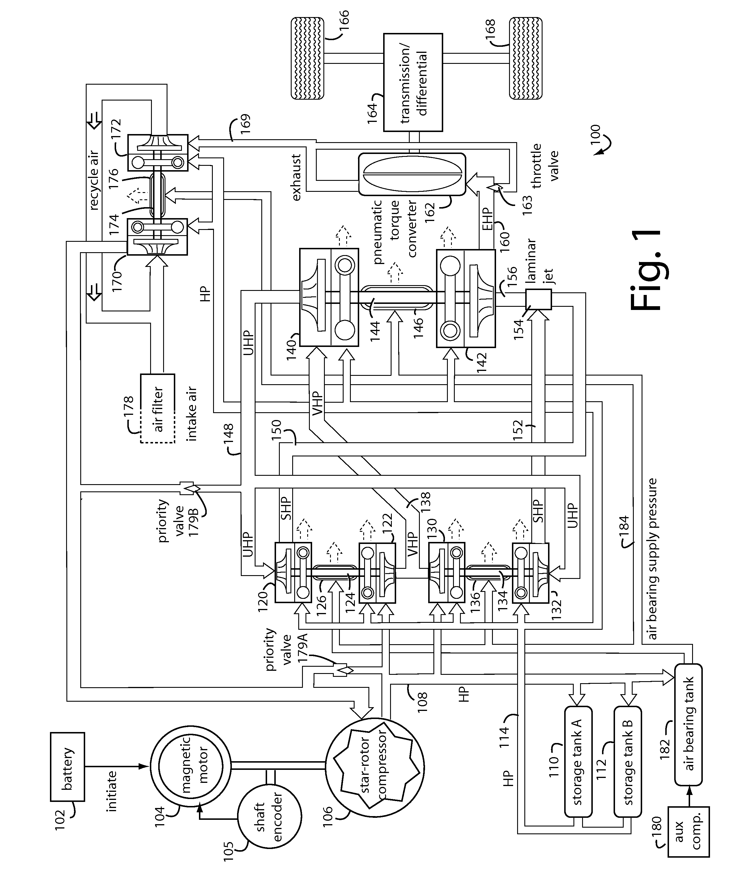
[0025]FIG. 1 represents a magnetic air car embodiment of the present invention, and is referred to herein by the general reference numeral 100. The magnetic air car 100 includes a 12-VDC storage battery 102 to start a magnetic motor 104 by energizing the windings of an internal starter motor. A shaft encoder 105 provides timing information back to the magnetic motor 104 for the proper synchronization of electric pulses to the stator windings.

[0026]The magnetic motor, once brought up to its starting speed, drives a star-rotor compressor 106. The star-rotor type compressors have rotors which are synchronized by gears not to touch one another during operation.

[0027]In one embodiment of the present invention, battery 102 includes a sodium free complex silicon salt electrolyte as described in PCT published patent application WO 01 / 13454 A1, published Feb. 22, 2001. Greensaver Technology Corporation (Ningbo, China) says they hold a patent for their so-called GREENSAVER BATTERY. Silicone B...


PUM


Abstract

A magnetic motor automobile carries a magnetic motor and star rotor compressor to pack high-pressure input air into its on-board storage tanks. The compressor and storage tanks deliver the high-pressure working air and operational flows to several stages of compressors that boost the pressures during driving to very high-pressure, then ultra high-pressure, then super high-pressure, and finally to extremely high-pressure. A pneumatic torque converter uses jets of the extremely high-pressure to turn an input shaft of a transmission and differential. These, in turn, drive the powered wheels of a car.

Description

CO-PENDING APPLICATION[0001]This Application is a continuation-in-part of U.S. patent application Ser. No. 12 / 344,242, filed Dec. 25, 2008, and titled, MAGNETIC AIR CAR, and which will issue as U.S. Pat. No. 8,056,665, on Nov. 15, 2011.MAGNETIC MOTOR AND AUTOMOBILE[0002]1. Field of the Invention[0003]The present invention relates to magnetic motors for automobiles, and more particularly to propulsion systems for automobiles that use magnetic motors to compress air on-board and that then use the compressed air to propel a vehicle.[0004]2. Description of the Prior Art[0005]Gasoline and diesel internal combustion, steam, electric, compressed air, and turbine engines have all been used to propel various kinds of cars and other vehicles. The range of these vehicles is limited by how much fuel or energy can be carried on-board until the next fill-up or recharge. Better engine efficiencies can improve the range, the more efficient the engine, the greater will be the range given the same am...

Claims


Application Information

Patent Timeline
Patent Type & Authority Applications(United States)
IPC IPC(8): F16D31/02H02K1/12H02K47/00H02P6/14H02K21/12
CPCB60K6/12B60K6/26B60K17/10B60K2006/123B60L1/003Y02T10/6208Y02T10/7005B60L11/002B60L11/18B60L11/16B60L50/90B60L50/30Y02T10/62Y02T10/70
Inventor LEONARD, STEVENDONOVAN, PAUL
Owner MAGNETIC AIR MOTORS
Why Eureka
Try Eureka