Braking mechanisms

a braking mechanism and eddy current technology, applied in the field of eddycurrent braking mechanism, can solve the problems of limiting rotation speed, high braking torque, and clear friction between the brakes, and achieve the effects of increasing the relative speed, increasing the braking effect, and multiplying the relative velocity between the conductive member

Active Publication Date: 2012-03-08
EDDY CURRENT PARTNERSHIP
View PDF18 Cites 93 Cited by
  • Summary
  • Abstract
  • Description
  • Claims
  • Application Information

AI Technical Summary

Benefits of technology

[0072]The braking effect may be increased by increasing the number of conductive members moving through the applied magnetic field. However, the number and size of the conductive members will be limited by the size and weight constraints of the application. Thus, for example, in auto-belay applications, preferably three said conductive members are provided.
[0123]The configuration of the braking torque applied to both the ‘linear’ and ‘pivoting’ (i.e. with pivoting conductive member) embodiments can be modified and calibrated by changing the level of bias thereby providing an effective means of accommodating applications requiring specific braking torque profiles.

Problems solved by technology

A higher relative velocity between the conductor and magnets will result in a higher braking torque thereby potentially limiting the rotation speed.
Friction-brakes clearly have disadvantages compared with eddy-current brakes as the frictional contact involves substantial heat generation, wear and corresponding safety problems.
Hydraulic dampening mechanisms are expensive and vulnerable to leaks, pressure and calibration problems.
However, none of the prior art systems appear suitable for application in an auto-belay or other applications where a constant speed of rotation is required where the torque applied may vary.
While the Sugimoto device may be more effective than simple plate-type systems it cannot be adjusted to vary the braking force applied and relies on an overdrive mechanism to improve braking force i.e. by increasing the relative speed between disc and magnetic field.
The overdrive mechanism adds to cost, complexity, size, wear, increased heat generation and possibility of failure.
However, the gear mechanism constrains the limits of size and thus the degree of miniaturisation possible.
The Sugimoto device is thus undesirable for auto-belays which require a compact device with safe, reliable operation during frequent, and / or prolonged use.
Thus, these devices prove inconvenient in applications that need to accommodate different applied torques.
The Muramatsu device may be adjustable to vary the braking effect and the maximum braking torque achievable but is still constrained by the size of the disc and strength of magnets, thus proving inconvenient where a smaller size is advantageous, e.g. for auto-belay devices.
As with the Muramatsu device, the braking effect of the Imanashi et al. cannot be automatically adjusted to accommodate different applied torques.
The Reiser system is reliant on a static supporting arrangement and varying weight change in the spool and is thus unsuitable for an auto-belay device.
Furthermore, the braking effect of the Reiser device varies only with rotation speed and magnetic field strength and not applied torque.
The Gersemsky et al. system, while fulfilling its purpose, is limited in adaptability as the braking torque applied is dependant on only the relative velocity (proportional to speed of rotation and radius to axis of rotation) of the magnets, Furthermore, auto-belay devices typically require braking in only one direction and thus universal braking devices such as the Gersemsky et al. system may be unsuitable.

Method used


Image

  • Braking mechanisms
  • Braking mechanisms
  • Braking mechanisms

Examples


Embodiment Construction

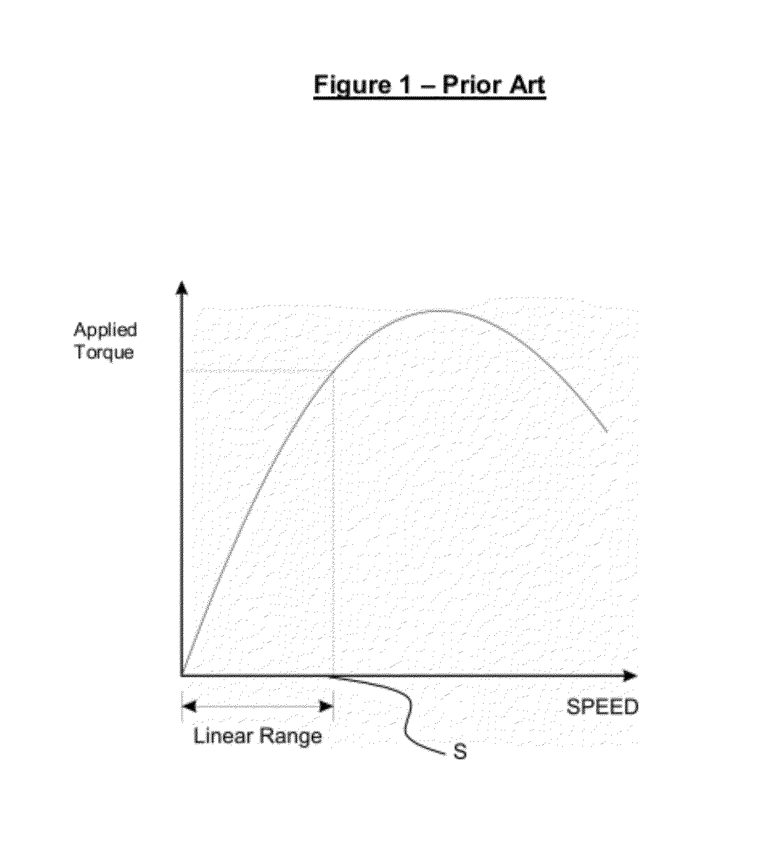
[0175]FIG. 1 shows a plot of Torque vs. Speed for an exemplary prior art eddy-current braking mechanism that utilises a conductive disc configured to rotate in a magnetic field. Eddy-currents are induced in the disc when the disc rotates and a reactive magnetic field is generated opposing the applied magnetic field. The opposing magnetic fields create a reactive force opposing movement of the disc through the magnetic field.

[0176]The magnitude of the braking torque applied to the disc is dependant on the magnetic field strength and the speed of rotation, thus as speed increases, the braking torque also increases. This system will limit the speed to a certain level depending on the applied torque. However, the braking torque and therefore equilibrium speed are only linearly proportional to the speed within a predetermined operating range (as shown in FIG. 1), until a threshold ‘characteristic speed’ (S) is reached where the braking torque becomes non-linear and peaks before beginning...


PUM


Abstract

An eddy-current braking mechanism including a rotor, rotatable about a rotor axis; at least one electrically conductive member coupled to the rotor for rotation therewith; at least one magnet configured to apply a magnetic field extending at least partially orthogonal to the plane of rotation of the conductive member, and characterised in that upon rotation of the rotor, the conductive member is configured to move at least partially radially from the rotor axis into the applied magnetic field.

Description

TECHNICAL FIELD[0001]The present invention relates to improvements in and relating to braking mechanisms and more particularly to an improved eddy-current braking mechanism.BACKGROUND ART[0002]Eddy-current braking systems are used in a range of applications to provide non-contact braking and offer a significant advantage over conventional friction brakes as there is no frictional contact between the braking surfaces.[0003]Eddy-current brakes function on the principle that when a conductor moves through a magnetic field (or vice-versa) the relative motion induces circulating ‘eddies’ of electric current in the conductor. The current eddies in turn induce magnetic fields that oppose the effect of the applied magnetic field. Eddy-current brakes thus utilise the opposing magnetic fields to act as a brake on movement of the conductor in the magnetic field, or vice versa. The strength of the eddy current magnetic field, and therefore the opposing force is dependant on a number of factors ...

Claims


Application Information

Patent Timeline
Patent Type & Authority Applications(United States)
IPC IPC(8): H02K49/04B65H75/44A63B29/00B65H75/48
CPCA62B1/08H02K7/116H02K16/005H02K49/046H02K7/12H02K2213/09A62B1/10H02K49/04H02K49/10H02K7/104F16D59/00A63B69/0048
Inventor ALLINGTON, CHRISTOPHER JAMESDIEHL, ANDREW KARLROBERTSON, BRUCE JOHN
Owner EDDY CURRENT PARTNERSHIP
Why Eureka
Try Eureka