Hybrid switch for resonant power converters

a technology of resonant power converter and hybrid switch, which is applied in the direction of electronic switching, power conversion system, pulse technique, etc., can solve the problems of inefficient supply of any significant current, cyclic, and parts of the switching cycle may be less efficient, so as to reduce conduction loss and constant voltage drop

Active Publication Date: 2012-03-08
VIRGINIA TECH INTPROP INC
View PDF5 Cites 60 Cited by
  • Summary
  • Abstract
  • Description
  • Claims
  • Application Information

AI Technical Summary

Benefits of technology

[0014]In accordance with another aspect of the invention, a method of reducing conduction losses in a high current switching circuit is provided comprising controlling two switches to conduct concurrently, wherein one of the two switches exhibits a substantially resistive voltage drop as a...

Problems solved by technology

Maintaining a DC voltage at a particular desired level within a small tolerance, however, generally requires regulation by an active circuit since practical filters generally cannot hold a DC voltage within tolerances generally required by electronic devices.
While analog voltage regulators have been known for many years, they are inefficient to provide any significant current because of the voltage drop developed across them and the power they consume for that reason.
However, such switching is necessarily cyclic and some portions of the switching cycle may be less efficient than others due to the instantaneous conduction conditions in the regulator or power converter circuit.
For example, at light loads where conduction losses are reduced, the amount of power consumed by the rapid switching, referred to as switching losses, becomes a significant fraction of the total power consumption of the regulator or power converter.
Conversely, at heavy loads where high current is drawn through the regulator or power converter, conduction losses in the switches, generall...

Method used


Image

  • Hybrid switch for resonant power converters
  • Hybrid switch for resonant power converters
  • Hybrid switch for resonant power converters

Examples


Embodiment Construction

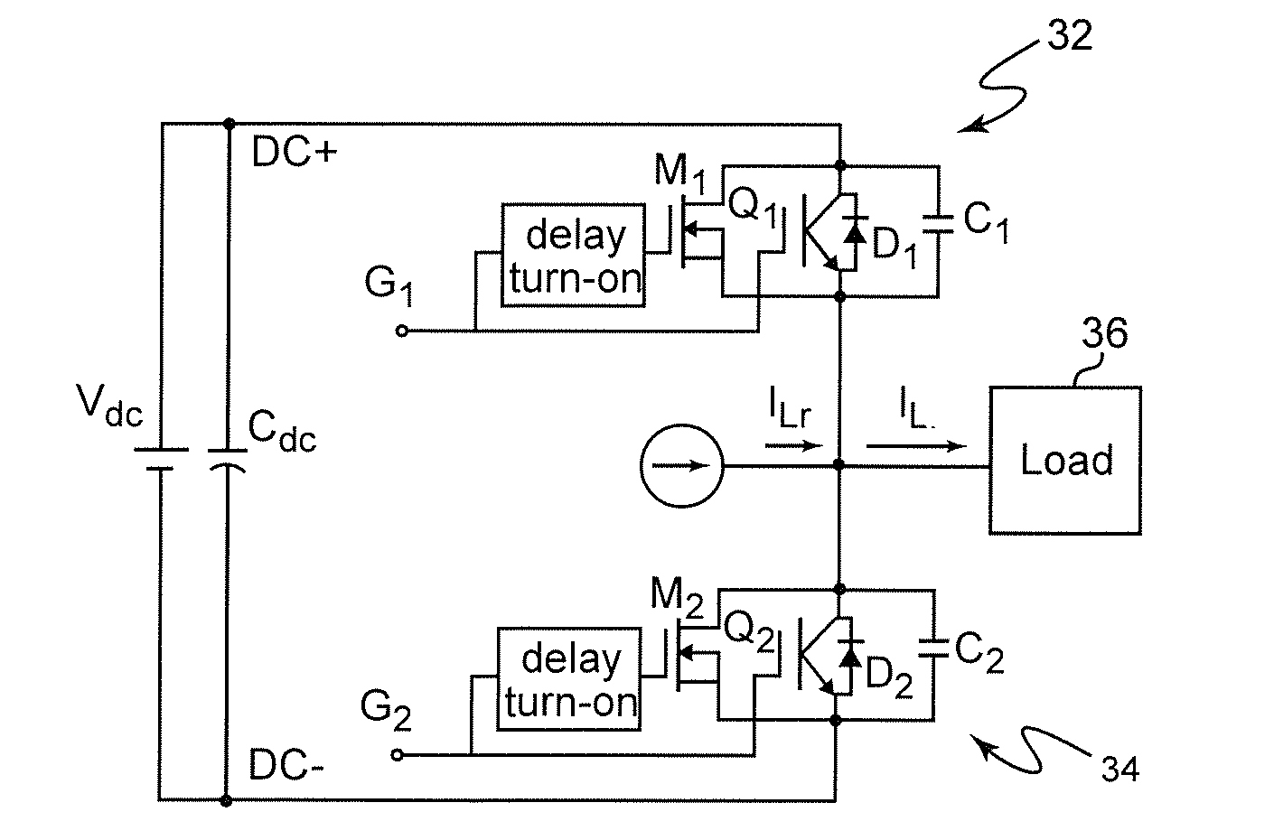
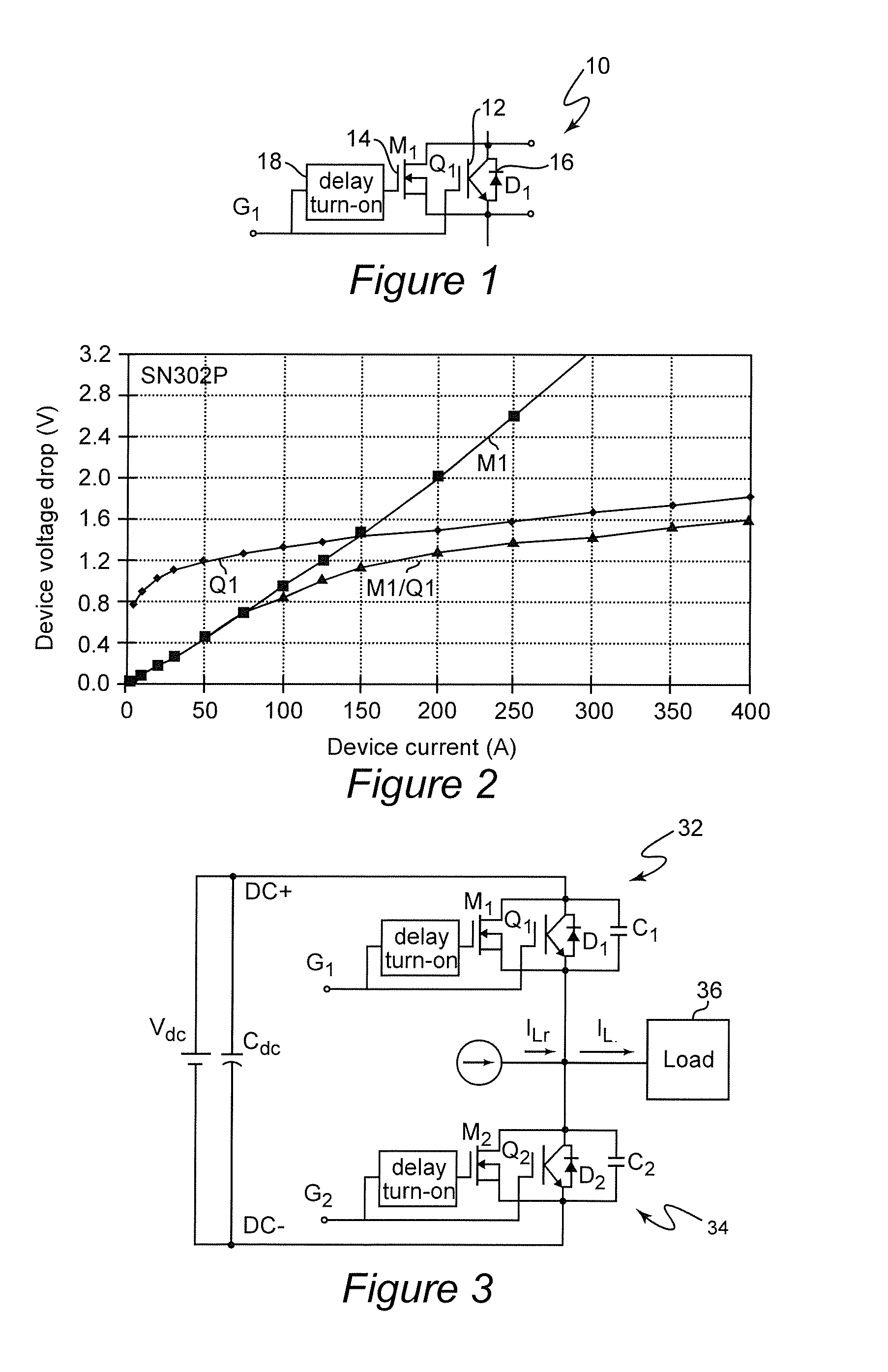
[0026]Referring now to the drawings, and more particularly to FIG. 1, there is shown a schematic diagram of the hybrid switch 10 in accordance with the invention. The hybrid switch 10 essentially comprises a power insulated gate bipolar transistor (IGBT—Q1) 12 and a power MOSFET 14 (M1) having the conduction terminals and control terminals of both transistors essentially connected in parallel. For soft switching, the IGBT will also preferably have a diode D1 (16) connected in parallel with the conduction terminals thereof. MOSFET 14 inherently includes a similarly connected diode referred to as a body diode. Both transistors are controlled by the same signal G1 although it is preferred and generally necessary in very high voltage, high power applications to provide a turn-on delay 18 in the application of signal G1 to MOSFET 14 as will be discussed in greater detail below. No delay is generally required for turn-off of MOSFET 14 (M1) and the delay structure 18 can be as simple as a ...


PUM


Abstract

A hybrid switch comprising two semiconductor switches connected in parallel but having different voltage drop characteristics as a function of current facilitates attainment of zero voltage switching and reduces conduction losses to complement reduction of switching losses achieved through zero voltage switching in power converters such as high-current inverters.

Description

CROSS-REFERENCE TO RELATED APPLICATIONS[0001]This application claims benefit of priority of U.S. Provisional Application 61 / 372,127, filed Aug. 10, 2010, which is hereby incorporated by reference in its entirety.STATEMENT OF GOVERNMENT INTEREST[0002]This invention was made with government support under Contract No. DE-FC26-07NT43214 awarded by the Department of Energy. The U.S. Government may have certain rights in this invention.FIELD OF THE INVENTION[0003]The present invention generally relates to semiconductor devices capable of switching high currents and, more particularly, to a hybrid switching device or circuit particularly suited for use in high power switching circuits such as resonant power converters to increase the efficiency thereof.BACKGROUND OF THE INVENTION[0004]At the present time, most power distribution is achieved using high voltage alternating current (AC) such that resistive losses in long power distribution lines can be reduced to acceptable levels. Alternatin...

Claims


Application Information

Patent Timeline
IPC IPC(8): H02M7/5387H03K17/567H02M7/00H02M7/537H03K17/284H03K17/687
CPCH02M7/797H02M2001/0048Y02B70/1491H03K17/567Y02B70/1441H03K17/06H03K17/12H03K17/164H03K17/168H02M1/0048Y02B70/10
Inventor LAI, JIH-SHENGYU, WENSONG
Owner VIRGINIA TECH INTPROP INC
Why Eureka
Try Eureka