
Thermal Type Air Flow Meter

a flow meter and air technology, applied in the direction of volume/mass flow measurement, measurement devices, instruments, etc., can solve the problems of increasing assembly man-hours, increasing the number of components, and disadvantageous to achieve the complicated structure of secondary air passages, so as to prevent variations in the flow rate measurement accuracy

Active Publication Date: 2012-03-15
HITACHI ASTEMO LTD
View PDF11 Cites 30 Cited by
  • Summary
  • Abstract
  • Description
  • Claims
  • Application Information

AI Technical Summary

Benefits of technology

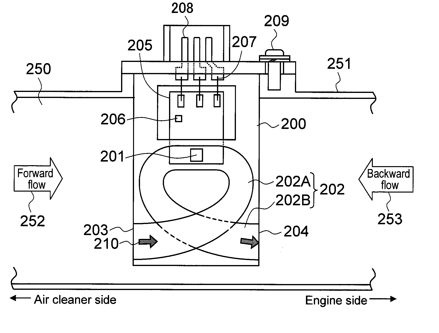
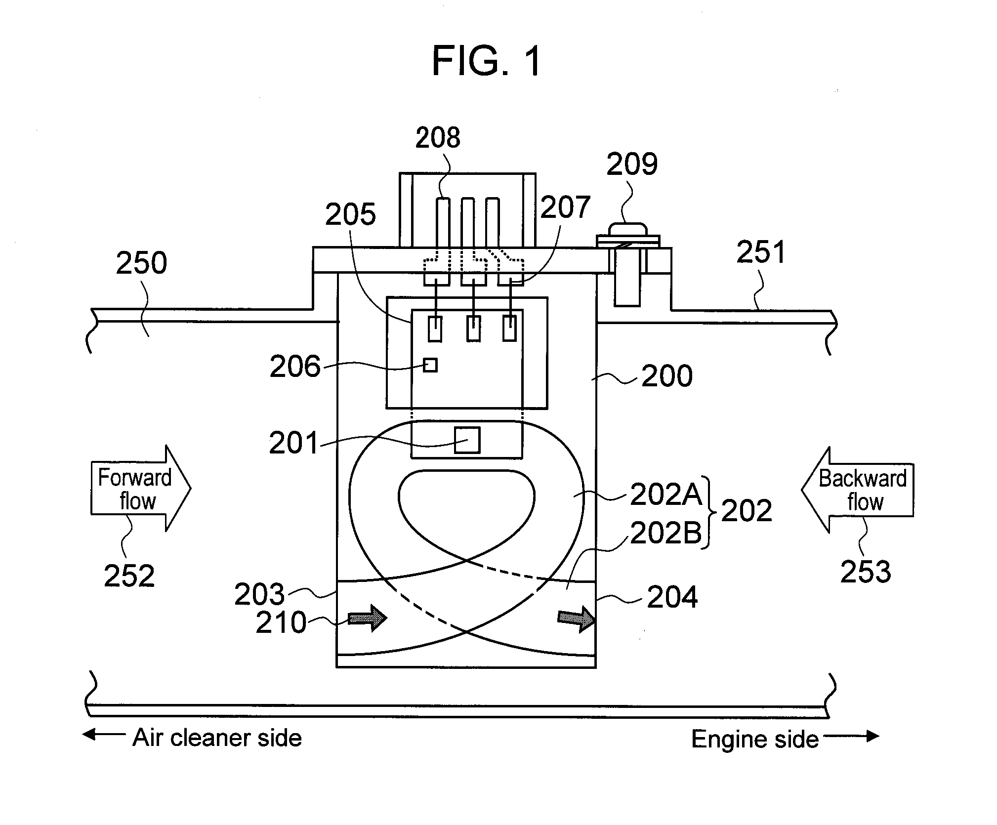
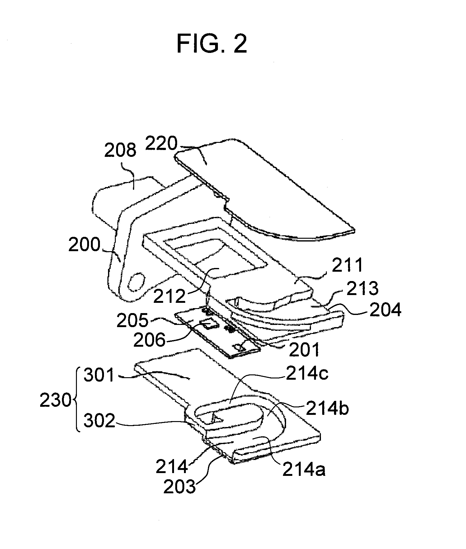
[0016]In order to solve the above-mentioned problems, the present invention provides a thermal type air flow meter including: a housing member placed in an intake passage of an internal combustion engine; a plate-like base member that is fixed to the housing member and includes a secondary passage into which part of air passing through the intake passage flows; a flow rate detecting element placed in the secondary passage; and a circuit board that is electrically connected to the flow rate detecting element, receives an input of an amount of heat radiation from the flow rate detecting element, and outputs a signal according to an air flow rate. The base member is formed of a synthetic resin material and includes: a board fixing part to which the circuit board is fixed; a secondary passage constituting part that is integrally formed so as to be continuous with a leading end part of the board fixing part and constitutes the secondary passage in cooperation with the housing member; and a reinforcing structure that is provided at at least a connection portion between the board fixing part and the secondary passage constituting part and enhances strength of the base member.
[0017]With the thermal type air flow meter according to the present invention, the base member is formed of the synthetic resin material and includes: the board fixing part to which the circuit board is fixed; the secondary passage constituting part that is integrally formed so as to be continuous with the leading end part of the board fixing part and constitutes the secondary passage in cooperation with the housing member; and the reinforcing structure that is provided at at least the connection portion between the board fixing part and the secondary passage constituting part and enhances the strength of the base member. Accordingly, the strength of the flat plate-like base member is enhanced by the reinforcing structure.
[0019]Accordingly, it is possible to prevent a trouble of attachment to the housing member and a trouble of attachment of the circuit board due to the warpage deformation and also possible to prevent variations in the flow rate measuring accuracy.

Problems solved by technology

The increase in the number of components, however, leads to an increase in cost, and in order to achieve the reduction in cost, it is necessary to achieve the complicated structure without increasing the number of components.
In addition, the metal base is formed by pressing a flat plate-like metal material, and hence the metal base is advantageous to maintain a flat surface for the bonding and the like but is disadvantageous to achieve the complicated structure of the secondary air passage.
Accordingly, it is conceivable to form by resin molding only a portion of the secondary air passage constituted by the metal base member similarly to the secondary air passage member, but in order to place the flow rate detecting element inside of the secondary air passage, this portion needs to be newly prepared as a separate component, resulting in the increase in the number of components and the increase in assembly man-hours, and the increase in cost of the thermal type air flow meter cannot be avoided.
Under the circumstance, if such a thick part and such a thin part are formed as the same molded component, thermal contraction becomes uneven between the thick part and the thin part at the time of the molding, and a warpage phenomenon may occur at a boundary between the thick part and the thin part.
This warpage deformation causes a trouble in bonding properties of the housing and the circuit board, and moreover, variations in a warpage amount lead to variations in a shape of a flow rate measuring unit.
As a result, a new problem arises that the flow rate measuring accuracy also varies.

Method used


Image

  • Thermal Type Air Flow Meter
  • Thermal Type Air Flow Meter
  • Thermal Type Air Flow Meter

Examples


Embodiment Construction

[0032]Embodiments of the present invention are described in detail with reference to the attached drawings.

[0033]First, an operation principle of a representative thermal type air flow meter including a heat-generating resistor is described as an example of an intake air measuring apparatus.

[0034]FIG. 11 is a schematic configuration circuit diagram illustrating the operation principle of the thermal type air flow meter.

[0035]A drive circuit of the thermal type air flow meter is roughly formed of a bridge circuit and a feedback circuit. The bridge circuit is constructed by a heat-generating resistor RH for measuring an intake air flow rate, a temperature-sensitive resistor RC for compensating an intake air temperature, and resistors R10 and R11, and a heating current Ih is caused to flow through the heat-generating resistor RH such that a constant temperature difference is maintained between the heat-generating resistor RH and the temperature-sensitive resistor RC, while performing f...


PUM


Abstract

A thermal type air flow meter that is capable of suppressing deformation of a base member at the time of molding is disclosed, to thereby secure dimension accuracy and reduce an influence of a dimension change on measuring accuracy. The meter includes a housing member placed in an intake passage of an internal combustion engine, and a base member fixed to the housing member and includes a secondary air passage into which part of air passing through the intake passage flows. The base member is a plate-like resin molded component formed of a synthetic resin material and includes a reinforcing structure integrally formed between a board fixing part to which a circuit board is fixed; and a secondary passage constituting part formed at a leading end part of the board fixing part, the reinforcing structure enhancing strength of the base member.

Description

BACKGROUND OF THE INVENTION[0001]1. Field of the Invention[0002]The present invention relates to a thermal type air flow meter that measures the flow rate of air, for example, to a thermal type air flow meter that is attached to an intake pipe of an internal combustion engine and measures the flow rate of intake air supplied to an engine.[0003]2. Background Art[0004]A thermal type air flow meter that measures the flow rate of intake air supplied to an internal combustion engine is attached for use to part of an intake system of an internal combustion engine. The thermal type air flow meter has a mechanism of, for example, causing a flow rate detecting element such as a heat-generating resistor to generate heat and measuring the flow rate of passing air on the basis of the amount of heat radiation therefrom to the air. Accordingly, it is necessary to consider protection of the flow rate detecting element from contaminating substances and other factors during long-term use and securem...

Claims


Application Information

Patent Timeline
Patent Type & Authority Applications(United States)
IPC IPC(8): G01F1/68
CPCG01F5/00G01F1/6842
Inventor MORINO, TAKESHIKOBAYASHI, CHIHIROOKAMOTO, YUKIKONO, TSUTOMU
Owner HITACHI ASTEMO LTD
Learn More