
Self-contained, multi-fluid energy conversion and management system for converting solar energy to electric and thermal energy

a management system and solar energy technology, applied in the direction of heat collector mounting/support, thermal-pv hybrid energy generation, lighting and heating apparatus, etc., can solve the problems of complicated tubes/pipes, failure to provide a fast and efficient way to assemble the entire system, and circulating water in the panel may freeze and burst pipes, etc., to achieve simple, reliable and inexpensive

Active Publication Date: 2012-03-15
SOLEEVA SOLAR
View PDF6 Cites 19 Cited by
  • Summary
  • Abstract
  • Description
  • Claims
  • Application Information

AI Technical Summary

Benefits of technology

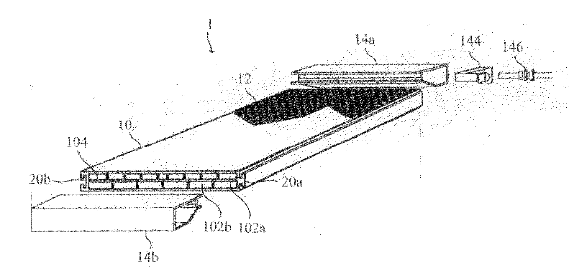
"The present invention provides a simple, reliable, and inexpensive solar energy converter for generating electric energy and heated fluid without complicated tubes / pipes. The converter includes a multi-layer assembly, a photovoltaic panel, and a manifold assembly. The multi-layer assembly has N layers separated by at least one separator floor, each layer has at least one channel adapted to contain a fluid stream, and each layer has a first opening and a second opening. The photovoltaic panel has a top surface and a bottom surface, and the bottom surface contacts the multi-layer assembly. The manifold assembly has N passages for containing the fluid streams, wherein the Kth passage is adapted to distribute the fluid stream to be heated into the channel of the Kth layer through the corresponding first opening and collect the heated fluid stream from the channel of the Kth layer through the corresponding second opening. The system also includes an umbilical connecting device for sharing the fluid streams contained in the manifold assemblies. The invention eliminates the need for assembled piping and provides a user to easily assemble multiple units of the system by mounting them on the frame to accommodate the user's needs."

Problems solved by technology

However, the system employs the tubes / pipes which are complicated to fabricate and failed to provide a fast and efficient way to assemble the entire system.
Besides, the system also suffers from cold and icy conditions, where the temperature is such that circulating water in the panel may freeze and burst the pipes.
Thus, the complicated tubes / pipes shall be a problem for maintaining such system.

Method used


Image

  • Self-contained, multi-fluid energy conversion and management system for converting solar energy to electric and thermal energy
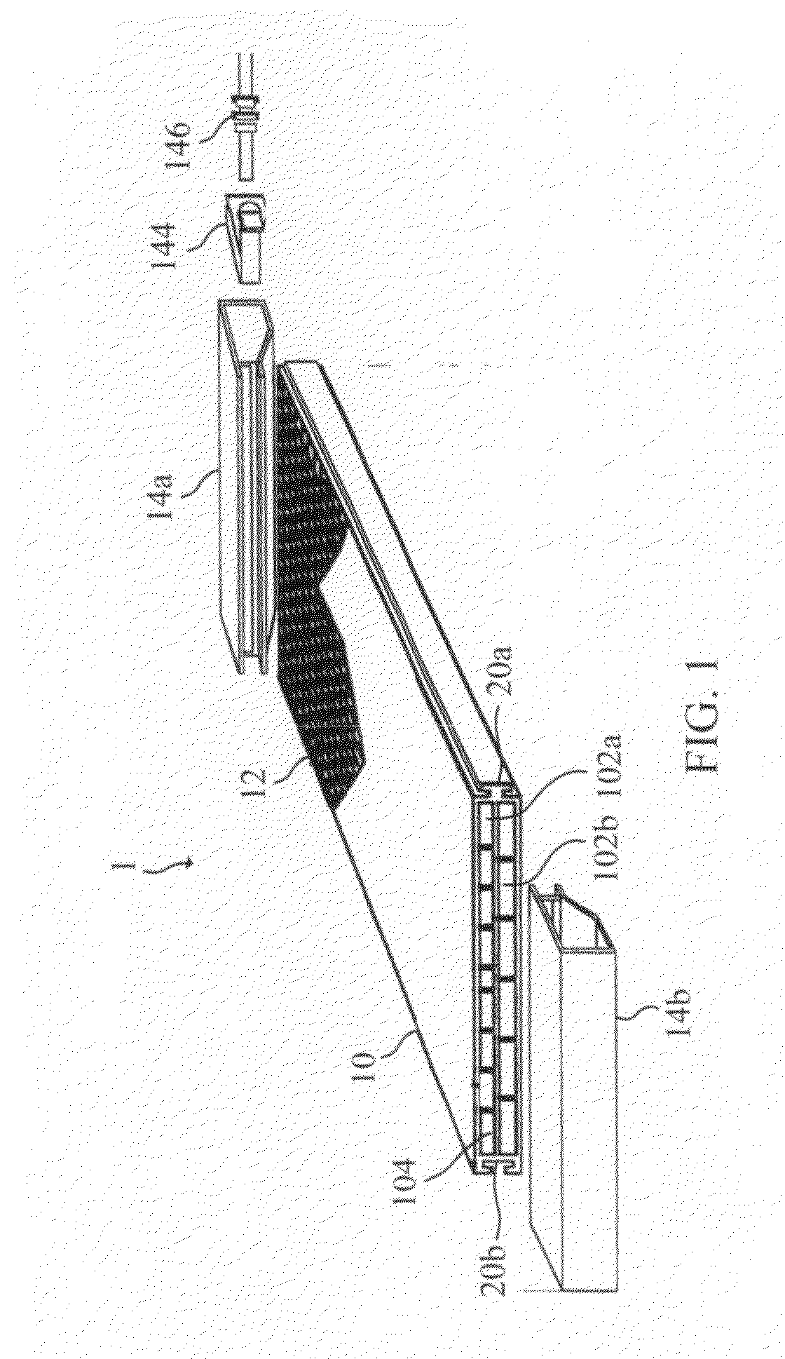
  • Self-contained, multi-fluid energy conversion and management system for converting solar energy to electric and thermal energy
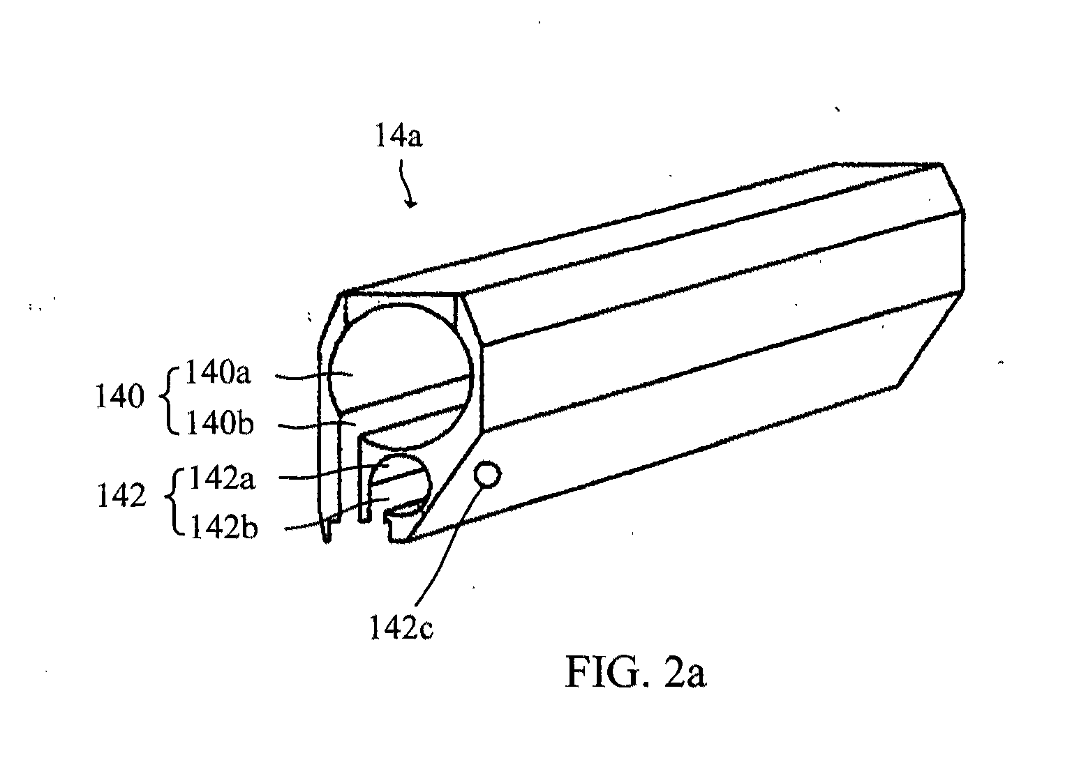
  • Self-contained, multi-fluid energy conversion and management system for converting solar energy to electric and thermal energy

Examples


example 1

[0088]This example illustrates how a system can be constructed. FIG. 11 illustrates a construction of a system, according to some embodiments. System 1100 includes protective glass cover sheets 1105 on the top side of the system 1107 and the bottom side of the system 1109 to protect the photovoltaic cells 1110, which generate the electrical power from solar energy. Air channels 1115 are designed into the system to conduct thermal energy generated in the system 1100 to a consumer in a gas phase. Water channels 1120 to conduct thermal energy generated in the system to the consumer in a liquid phase.

[0089]Heat transfer media 1125 can be included to conduct the heat from the photovoltaic cells 1110 to the gas and liquid phase. Note the gas and liquid phase are working fluids and may be any suitable liquid or gas known to one of skill that would function as desired in the transfer of heat from the system. Likewise, the heat transfer media can be any conductive media known to one of skill...

example 2

[0094]The systems taught herein include a single-unit, multimodal device combining both solar thermal and solar photovoltaic energy capture. The systems can be configured in modalities to enable capture of photo-voltaic generated energy from both the sun-facing side of the panel as well as reflected or scattered photovoltaic energy from photovoltaic structures mounted on the rear surface of the device. In addition, the unit captures an abundance of thermal energy that falls on the panel and is available for harvesting through multiple working fluid streams.

[0095]The thermal energy (heat) removal functions of the panel increases the energy density from the panel and serves to cool the photovoltaic cells. The photovoltaic cells are mounted on the panel and, as a result of the cooling of the system, provide a surprisingly consistent electrical power output.

[0096]FIG. 15 illustrates a consistent power output of a system having only one photovoltaic layer with a gas and liquid cooling me...

example 3

[0097]A system having (i) a photovoltaic layer on the front of the panel to capture and convert incident solar energy to electrical energy, along with (ii) an opposing photovoltaic layer on the back of the panel to capture and convert reflected and scattered solar energy was tested. It was discovered that by utilizing the rear side of the panel to capture reflected and scattered energy, the total energy from the system can approach twice the twice that of comparable products. Moreover, this energy density is further compounded through the capture of both electric and thermal energy through the multi-fluid heat transfer streams, providing the highest possible energy capture and conversion available in the industry today from such systems.


PUM


Abstract

The teachings generally relate to a system for converting solar energy into electrical energy and thermal energy using a self-contained system having a plurality of channels for the heat transfer using a respective plurality of fluids.

Description

CROSS-REFERENCE TO RELATED APPLICATIONS[0001]This application is a continuation-in-part of U.S. application Ser. No. 12 / 905,349, filed Oct. 15, 2010, and claims the benefit of U.S. Provisional Application No. 61 / 252,635, filed Oct. 16, 2009, each application of which is hereby incorporated herein by reference in its entirety.BACKGROUND OF THE INVENTION[0002]1. Field of the Invention[0003]The teachings generally relate to a system for converting solar energy into electrical energy and thermal energy using a self-contained system having a plurality of channels for the heat transfer using a respective plurality of fluids, in which the system provides an energy density that includes electricity and thermal energy directed to at least two fluids.[0004]2. Description of the Prior Art[0005]In general, traditional solar panels may have photovoltaic arrays placed on a flat plate for converting solar energy to electric energy, a series of tubes are secured to the flat plate for collecting sol...

Claims


Application Information

Patent Timeline
Patent Type & Authority Applications(United States)
IPC IPC(8): H01L31/058F24J2/24F24S10/70
CPCF24J2/0477F24J2/242F24J2/4647F24J2002/0092F24J2002/467H02S40/44Y02E10/50Y02E10/60H01L31/058H01L31/0422H02S20/00Y02E10/44F24S10/20F24S10/72F24S80/30F24S2020/17F24S2025/6007F24S10/70H01L31/042H01L31/056
Inventor AHLGREN, RALPH B.PETRY, KLAUSFLORES, A. MICHAEL
Owner SOLEEVA SOLAR
Learn More