Thermal processing apparatus with optimized structural support mechanism

a structural support mechanism and thermal processing technology, applied in electrical apparatus, ohmic-resistance heating, hot plate heating arrangements, etc., can solve the problems of reducing the thermal response time of the heating apparatus during ramp up, reducing the efficiency of heating and cooling of the substrate, and limiting the design

Inactive Publication Date: 2012-03-15
AGAMOHAMADI MITCH +1
View PDF6 Cites 9 Cited by
  • Summary
  • Abstract
  • Description
  • Claims
  • Application Information

AI Technical Summary

Benefits of technology

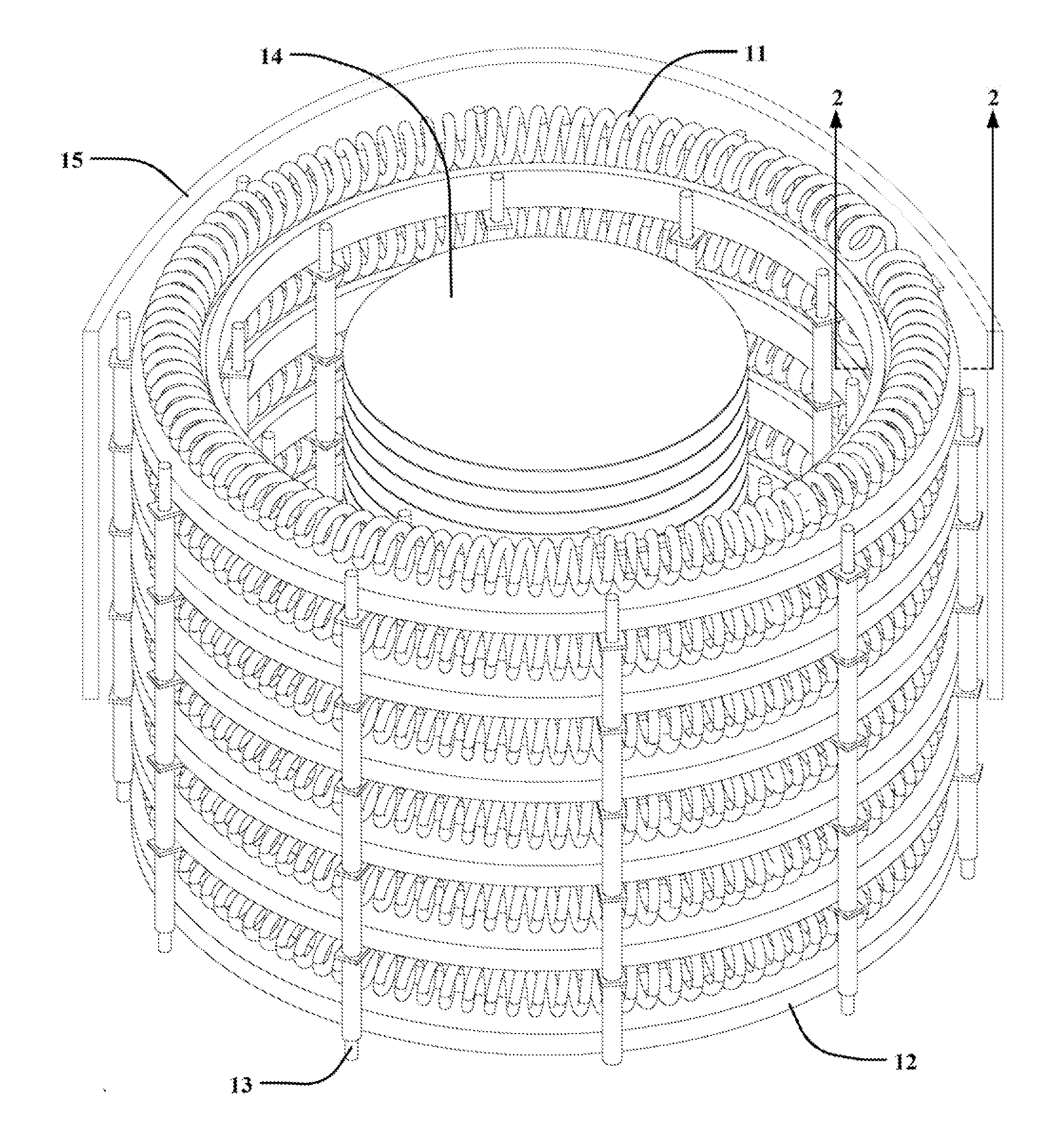
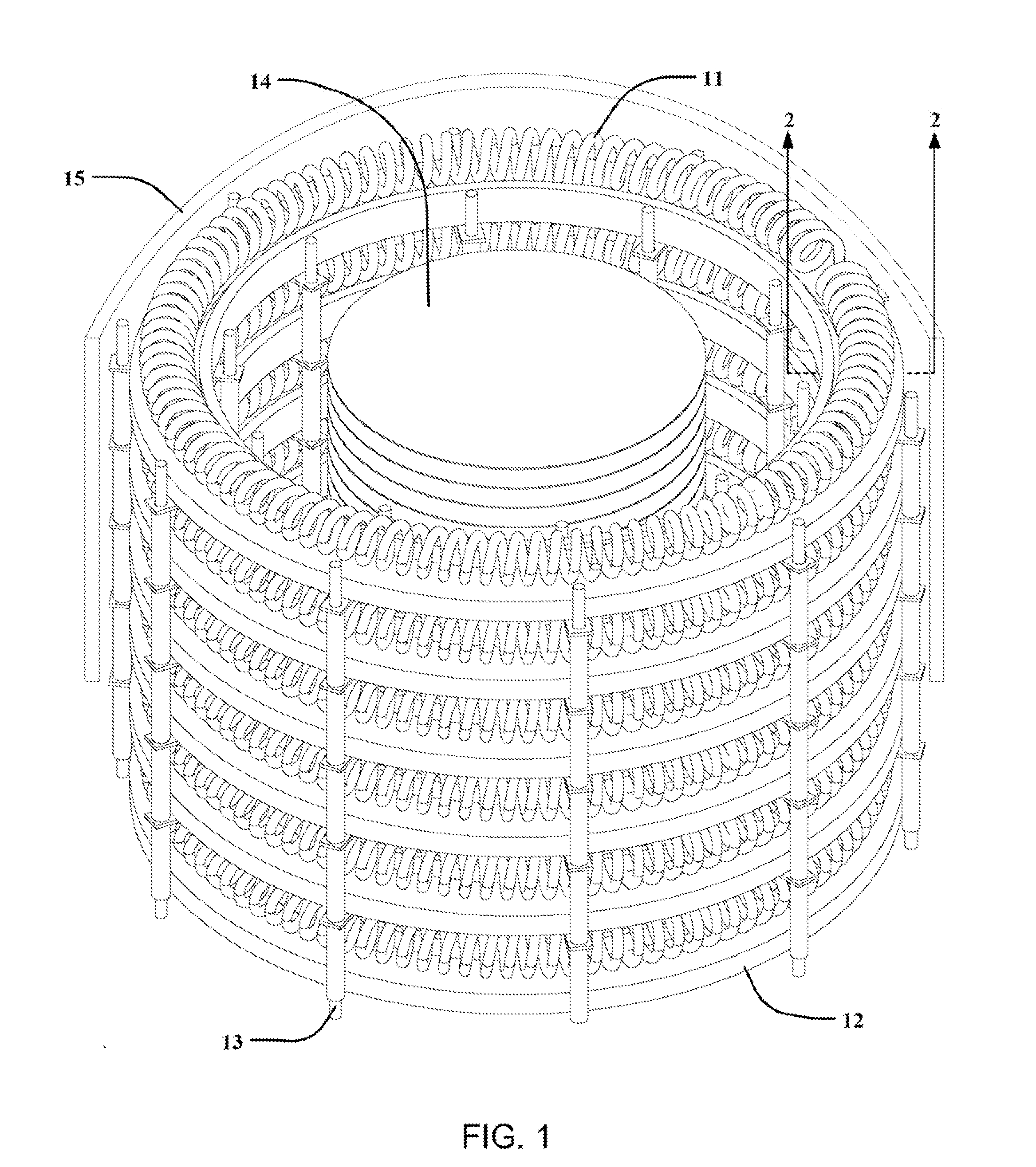
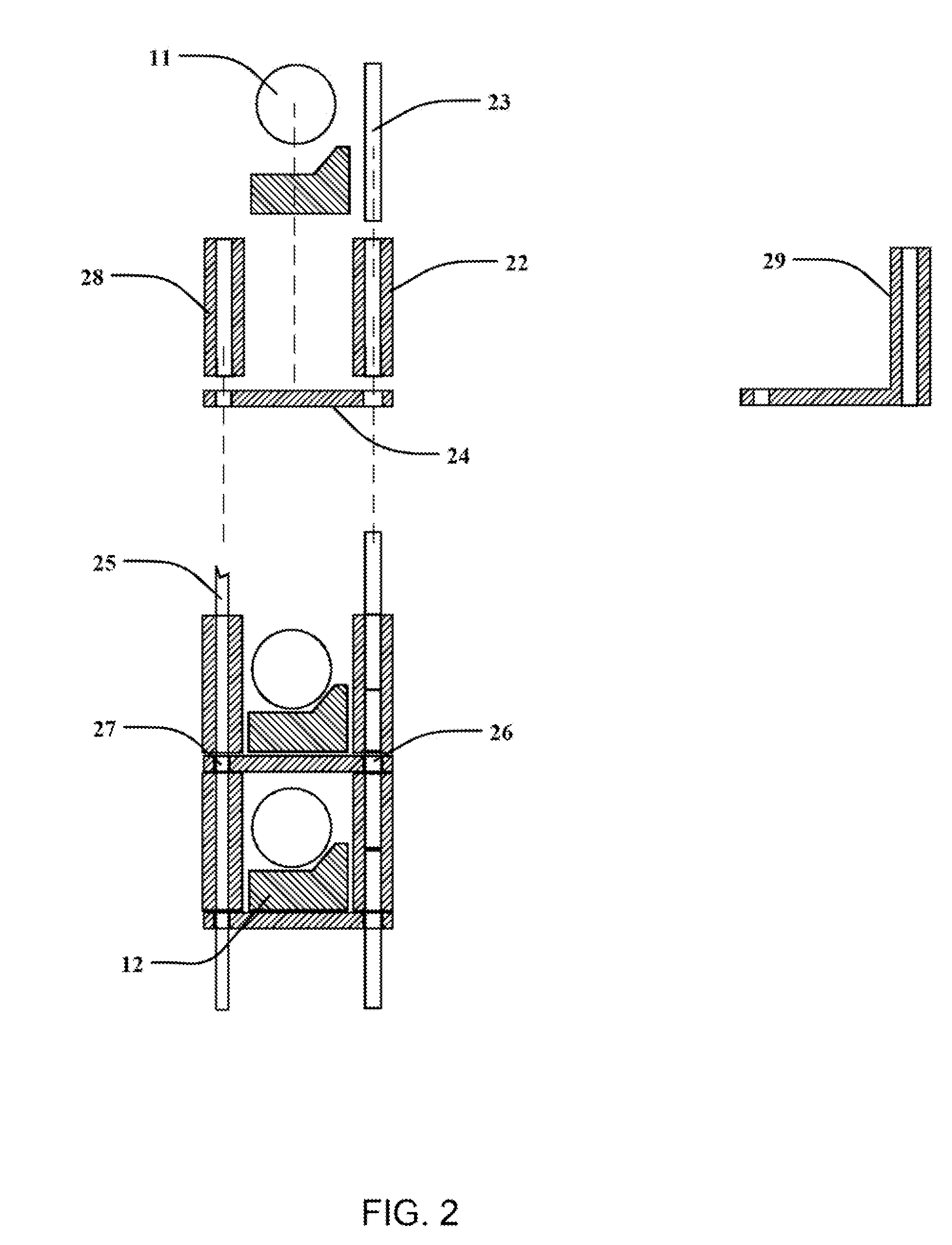
[0013]The skeletal structure has a minimum mass and provides structural support to carry the load of the heating elements and their circular support plates. As such, the support plates do not have any load bearing functions. This is true for the insulation material on the outside of heating element as well. Therefore, the choice of the material for the skeletal structure and insulation can be of a low mass to increase the efficiency of heating and cooling of the substrates.

Problems solved by technology

Several attempts have been made to reduce the amount of heat that is obstructed and stored, but these designs are restricted because of the load bearing requirements of the trays or blocks.
This furnace has a high thermal mass that stores extra energy in its own body, lowers the thermal response time of the heating apparatus during ramp up, increases the temperature stabilization time, and increases the cool down time.
These factors result in increased processing time and higher energy costs.
The coupling of load bearing and thermal dynamic functions require that the trays have higher density to carry the structural load, which lowers thermal response time, increases temperature stabilization time, and increases cool down time.
These factors result in increased processing time and higher energy costs.
This type of straight wire heating has a higher failure rate due to the expansion and elongation of the wire, which is constrained by the separators, causing buckling between the separator columns.

Method used


Image

  • Thermal processing apparatus with optimized structural support mechanism
  • Thermal processing apparatus with optimized structural support mechanism
  • Thermal processing apparatus with optimized structural support mechanism

Examples


Embodiment Construction

[0024]Illustrative embodiments of the invention are described below. The following explanation provides specific details for a thorough understanding of and enabling description for these embodiments. One skilled in the art will understand that the invention may be practiced without such details. In other instances, well-known structures and functions have not been shown or described in detail to avoid unnecessarily obscuring the description of the embodiments.

[0025]Unless the context clearly requires otherwise, throughout the description and the claims, the words “comprise,”“comprising,” and the like are to be construed in an inclusive sense as opposed to an exclusive or exhaustive sense; that is to say, in the sense of “including, but not limited to.” Words using the singular or plural number also include the plural or singular number respectively. Additionally, the words “herein,”“above,”“below” and words of similar import, when used in this application, shall refer to this appli...


PUM


Abstract

A thermal processing apparatus is disclosed which separates the load bearing components from the thermal components, improving heating time, cooling time, thermal response, and energy efficiency. The thermal processing apparatus comprises an array of cylindrical heating elements which rest on support plates of high temperature, low density material. The support plates and heating elements are then supported by a rigid skeletal structure for load bearing support.

Description

CROSS-REFERENCE TO RELATED APPLICATIONS[0001]This application claims the benefit of U.S. Provisional Patent Application No. 61 / 381,876, filed on Sep. 10, 2010, and incorporated herein by reference.STATEMENT REGARDING FEDERALLY SPONSORED RESEARCH AND DEVELOPMENT[0002]Not Applicable.FIELD OF THE INVENTION[0003]This invention relates to an improved thermal processing apparatus and process for heat treatment of semiconductor and solar substrates.DISCUSSION OF RELATED ART[0004]Heating systems are commonly used in many different applications. In the semiconductor and solar substrate processing industry, the heating systems are used to anneal or grow films with a specific gas or vapor onto a semiconductor substrate, or wafer, for achieving desired electrical properties. Furthermore, the annealing process is performed for a predetermined amount of time to cure the already grown films on the substrate to improve the film quality and performance.[0005]The wafers are typically heat treated in ...

Claims


Application Information

Patent Timeline
Patent Type & Authority Applications(United States)
IPC IPC(8): H05B3/68
CPCH01L21/67098
Inventor AGAMOHAMADI, MITCHSEDEHI, SAEED
Owner AGAMOHAMADI MITCH
Why Eureka
Try Eureka