
Front End Module Comprising an Antenna Tuner

a technology of antenna tuner and front end module, which is applied in the direction of transmission, measurement device, instruments, etc., can solve the problems of impaired isolation between the first and the second antennas, and achieve the effect of reducing the transmission power in the active signal path, reducing the risk of damage to the user, and maximising the impedance surroundings of the antenna

Inactive Publication Date: 2012-03-15
SNAPTRACK
View PDF7 Cites 50 Cited by
  • Summary
  • Abstract
  • Description
  • Claims
  • Application Information

AI Technical Summary

Benefits of technology

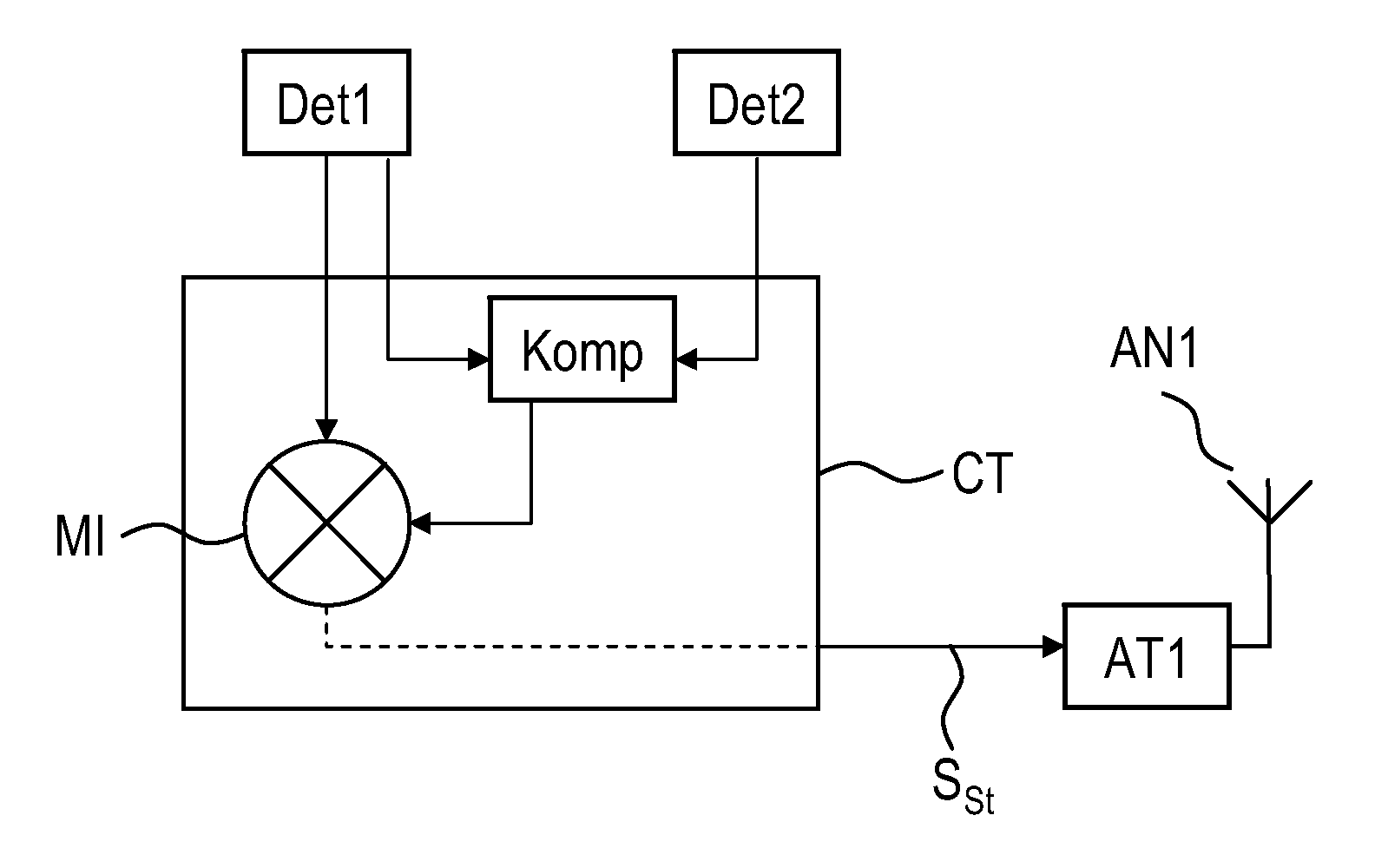
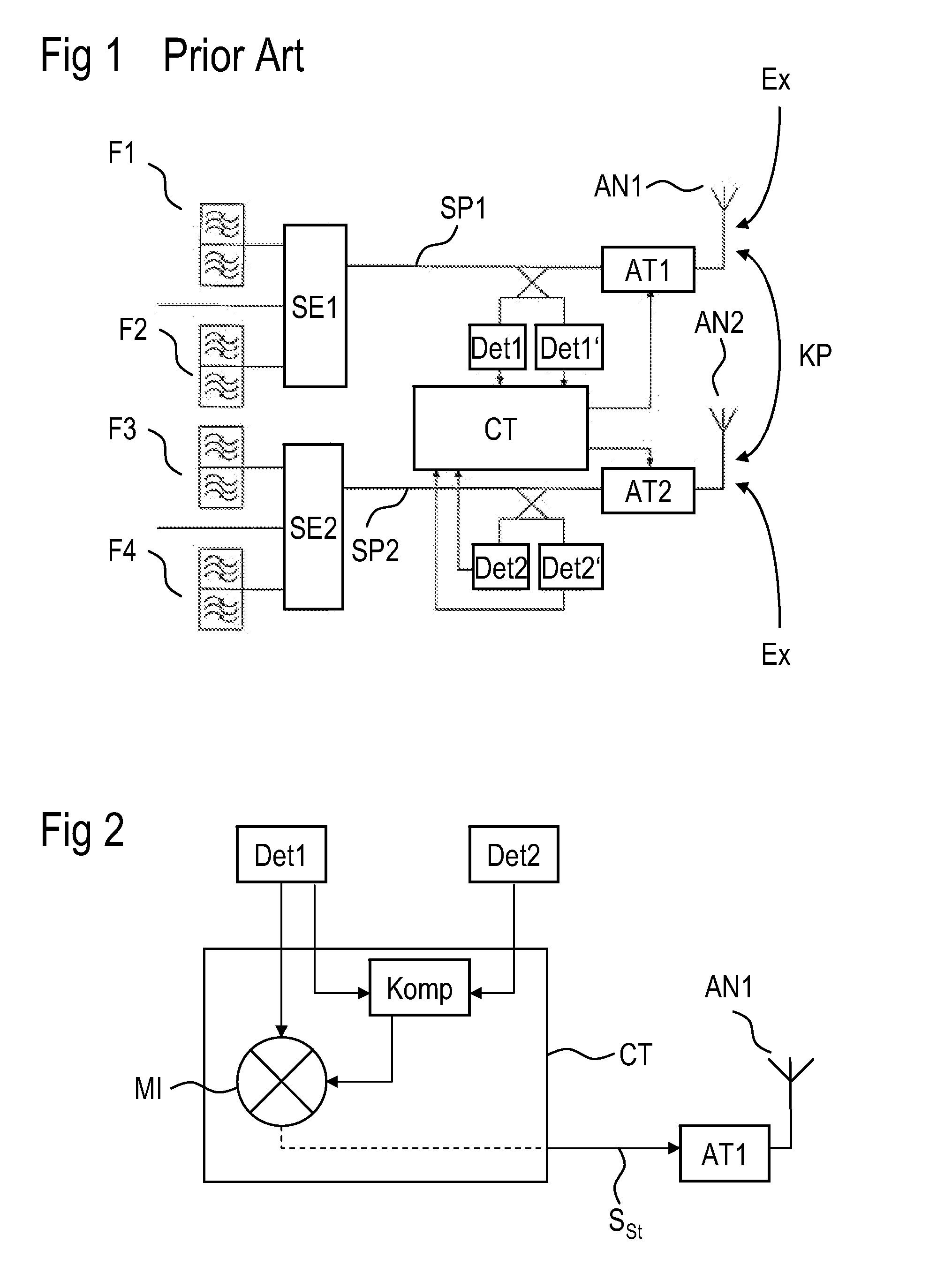
The present invention provides a front end module for improving the matching of an actively used antenna. The module includes two antennas and detectors for measuring the power reflected by the antennas. The detected power is used to determine the isolation between the two antennas and to generate a control signal for the antenna tuner. The control signal is used for closed-loop control of the antenna tuner, which allows for quicker and more precise matching of the antenna to the signal path. The module can be produced without additional hardware and can be easily integrated into existing front end modules. The invention also provides a method for identifying a mismatch more quickly and accurately, and a refinement of the module to improve the matching of the second antenna.

Problems solved by technology

It has now been found that as matching becomes poorer, the isolation between the first and the second antennas is also impaired.

Method used


Image

  • Front End Module Comprising an Antenna Tuner
  • Front End Module Comprising an Antenna Tuner
  • Front End Module Comprising an Antenna Tuner

Examples


Embodiment Construction

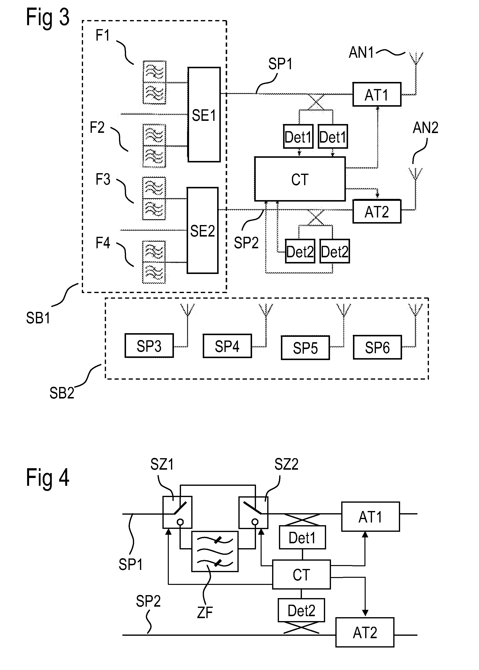
[0053]FIG. 1 shows a known front end module for a terminal of a wireless transmission / reception device with two antennas AN1, AN2. Each antenna is connected to an antenna tuner AT1 or AT2. The respective antenna tuner is connected to a switching unit SE1, SE2 which acts as an antenna switch and which can be used to selectively connect a plurality of different filters F1, F2, F3, F4 to the respective signal path SP1, SP2. The different filters are each associated with a frequency band for a mobile radio system. In FIG. 1, the filters F1-F4 are in the form of duplexers and have interconnected transmission and reception filters for the respective mobile radio system. However, it is also possible for the switching units SE1, SE2 in TDD mode to connect the signal paths SP1, SP2 selectively to a respective single filter for transmission or reception mode in a mobile radio system.

[0054]The respective signal path has the detectors DET1, DET2 (DET1′, DET2′) coupled to it, the detectors being...


PUM


Abstract

A front end module for a wireless transmission / reception device has two antennas and two signal paths connected thereto. A mismatch in the antenna is identified by monitoring the transmitted power and the reflected power in the active and passive signal paths and using the powers in a controller to generate a control signal for the antenna tuner. In this case, decreasing isolation between the first and second antennas and the first and second signal paths is identified, and is compensated for using different devices, in order to ensure faster and safer antenna matching.

Description

[0001]This patent application is a national phase filing under section 371 of PCT / EP2010 / 054750, filed Apr. 12, 2010, which claims the priority of German patent application 10 2009 018 648.4, filed Apr. 23, 2009, each of which is incorporated herein by reference in its entirety.BACKGROUND[0002]In modern terminals for mobile communication, use is increasingly being made of adaptive matching circuits for tuning the antenna. Such matching circuits are intended to be used to ensure that the terminal always has optimum antenna matching even in changing environments which influence the impedance of the antenna, the antenna matching being used to improve the transmission and reception operation of the terminal by saving transmission power and improving the reception quality. For this purpose, a detector for determining the reflected power is connected to the respective signal path, which is a transmission path or a hybrid transmission / reception path.[0003]The reflected power is a measure o...

Claims


Application Information

Patent Timeline
Patent Type & Authority Applications(United States)
IPC IPC(8): G01R29/08
CPCH01Q1/521H04B1/0458H01Q1/525H01Q5/314
Inventor TIKKA, PASIZELLER, GERHARD
Owner SNAPTRACK
Learn More