Image Processing Apparatus

a technology of image processing and apparatus, applied in the field of image processing apparatus, can solve the problems of difficult to realize images with a single imaging device, and achieve the effect of reducing costs and high precision

Inactive Publication Date: 2012-03-15
HITACHI AUTOMOTIVE SYST LTD
View PDF2 Cites 38 Cited by
  • Summary
  • Abstract
  • Description
  • Claims
  • Application Information

AI Technical Summary

Benefits of technology

[0015]With the present invention, headlights of oncoming cars, taillights of cars ahead, and pedestrians at night may be detected simultaneously and with high precision. Since it only requires the use of one small camera, costs may be reduced. In...

Problems solved by technology

Thus, ordinarily, it would be difficult...

Method used


Image

  • Image Processing Apparatus
  • Image Processing Apparatus
  • Image Processing Apparatus

Examples


embodiment 1

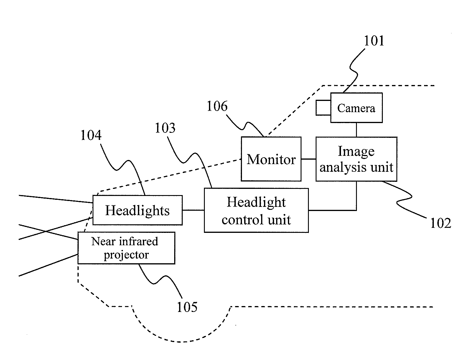
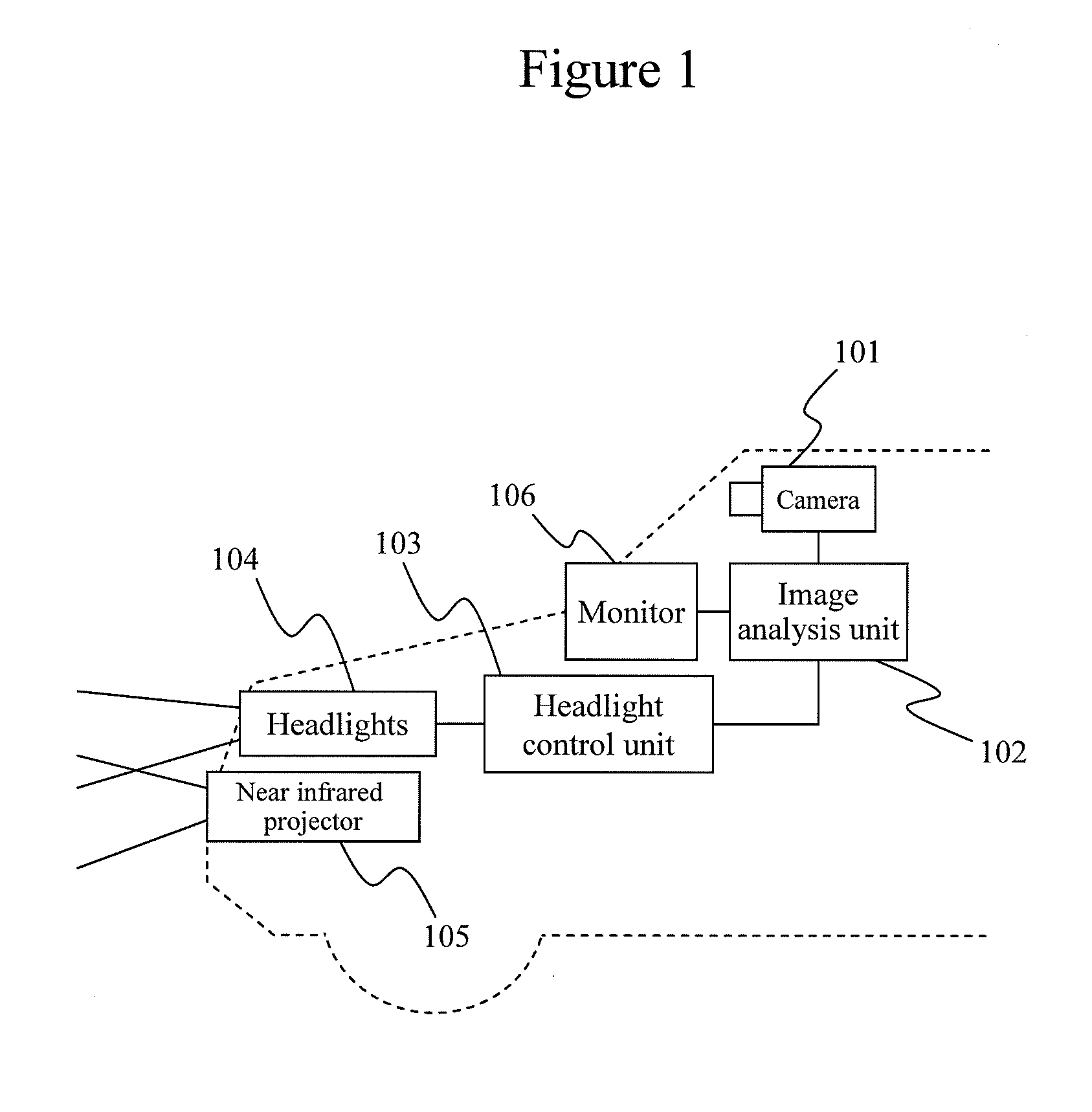
[0027]FIG. 1 shows an overview of the overall configuration of Embodiment 1 of the present invention. A camera 101 is installed near the rear-view mirror so as to be able to shoot forward of the vehicle. A vehicle forward image taken by the camera 101 is inputted to an image analysis unit 102. The image analysis unit 102 performs image processing, and, by way of example, if there is a vehicle ahead, analyzes the distance to that vehicle. Based on distance information with respect to the vehicle ahead, a headlight control unit 103 calculates voltage amounts to be applied to high beams and low beams of headlights 104, and supplies the calculated voltage to the headlights 104. The illumination distance for the headlights is thus controlled based on the distance to the vehicle ahead.

[0028]Thus, since the object here is to control the illumination distance for the headlights, instead of the voltage amounts mentioned above, the headlight control unit 103 may also calculate, and supply, cu...

embodiment 2

[0055]FIG. 9 shows a flowchart of a process of Embodiment 2. In Embodiment 2, a color image is generated and transferred in place of the visible grayscale image in Embodiment 1. In Embodiment 2, by excluding colored light when strong light is received from something other than headlights, e.g., from a traffic signal, it is possible to completely eliminate any erroneous identification of it as being a headlight. In the case of color, the conversion to a YUV signal is performed using conversion equations, namely Equations 11 to 13 below.

Y=0.299R+0.587G+0.114B  Equation 11

U=−0.169R−0.331G+0.500B  Equation 12

V=0.500R−0.419G−0.081B  Equation 13

[0056]With the exception of the points mentioned above, the remaining features of Embodiment 2 are the same as Embodiment 1, and descriptions will therefore be omitted.

embodiment 3

[0057]Embodiment 3 performs the exposure performed with the low-speed shutter in Embodiment 1 or Embodiment 2 once, and uses the result thereof for both visible color image generation and infrared grayscale image generation. FIG. 10 shows a flowchart of a process of Embodiment 3. Here, exposure is performed only once in step 1001. As a result, it is possible to reduce the transfer amount of image data, and to shorten the processing cycle.

[0058]With the exception of the points mentioned above, the remaining features of Embodiment 3 are the same as Embodiment 1 or 2, and descriptions will therefore be omitted.


PUM


Abstract

An image processing apparatus capable of detecting, simultaneously and with high precision, headlights of oncoming cars, taillights of cars ahead, and pedestrians at night, the image processing apparatus comprising: means that obtains first exposure data at a first shutter speed; means that obtains second exposure data at a second shutter speed that is slower than the shutter speed; means that obtains third exposure data at a third shutter speed that is slower than the first shutter speed; means that converts the first exposure data into a visible grayscale image; means that outputs the visible grayscale image; means that converts the second exposure data into a color image; means that outputs the color image; means that converts the third exposure data into an infrared grayscale image; means that outputs the infrared grayscale image; means that detects a headlight based on the visible grayscale image; means that detects a taillight based on the color image; and means that detects a pedestrian based on an image obtained by processing the infrared grayscale image and the color image.

Description

TECHNICAL FIELD[0001]The present invention relates to an image processing apparatus for use as a sensor for performing light distribution control, etc., of headlights for cars.BACKGROUND ART[0002]Methods of detecting headlights of oncoming cars or taillights of cars ahead with a camera in order to perform light distribution control for high beams / low beams of headlights at night have previously been proposed. By way of example, Patent Document 1 discloses an apparatus that detects headlights and taillights efficiently using color information of light spots within an image taken using a color camera. Light sources that cameras might capture at night are not restricted to headlights and taillights for which detection is desired. Instead, noise light sources that ought to be excluded, such as street lights, traffic lights, reflectors (reflector plates), etc., also exist. Since such noise light sources are brighter than the light of distant taillights that are to be detected, it is poss...

Claims


Application Information

Patent Timeline
IPC IPC(8): H04N7/18G06V10/143G06V10/147
CPCG08G1/16H04N7/18G06K9/00825G06K9/2018G06K9/209G06K9/00805H04N5/2353H04N5/2356H04N5/332H04N5/353H04N9/045G08G1/166G06V20/58G06V20/584G06V10/143G06V10/147H04N23/743H04N23/73H04N23/11H04N25/53
Inventor OTSUKA, YUJIMONJI, TATSUHIKO
Owner HITACHI AUTOMOTIVE SYST LTD
Why Eureka
Try Eureka