

Backlight Structure and Manufacturing Method Thereof
- Summary
- Abstract
- Description
- Claims
- Application Information
AI Technical Summary
Benefits of technology
Problems solved by technology
Method used
Image

Examples
first embodiment
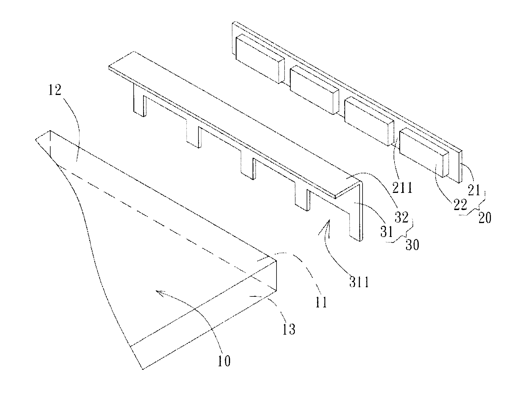
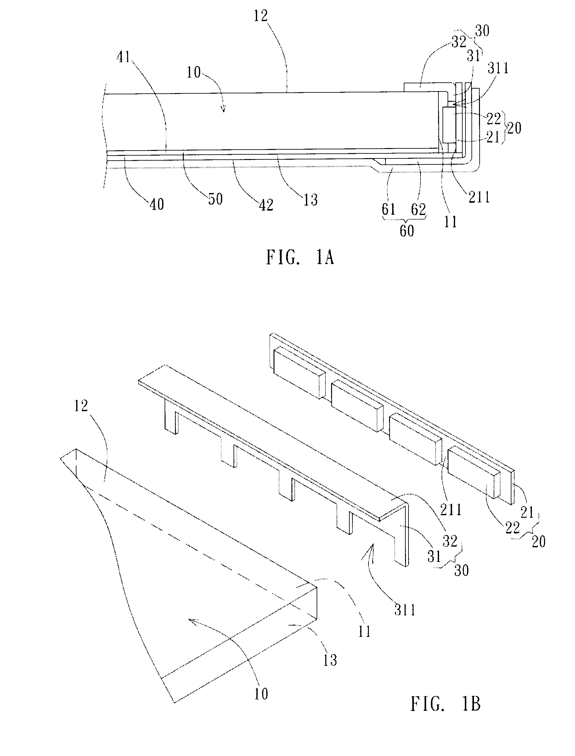
[0019]FIG. 1A is a schematic view of the backlight structure of the present invention. FIG. 1B is an exploded view of the backlight structure shown in FIG. 1A. As shown in FIGS. 1A and 1B, the backlight structure includes a light guide plate 10, a light source module 20, a reflective cover 30, a reflector 40, and a supporting structure 60. The light guide plate 10 has a light incident side 11, a light-exiting surface 12, and a bottom surface 13. The light-exiting surface 12 is a surface of the light guide plate 10 that faces upward; the bottom surface 13 is another surface of the light guide plate 10 that faces downward. The light incident side 11 is disposed on the sidewall of the light guide plate 10, wherein the light-exiting surface 12 and the bottom surface 13 are formed on two opposite ends of the light incident side 11, so that the light-exiting surface 12 and the bottom surface 13 are angularly connected to the light incident side 11.
[0020]The light source module 20 includes...
second embodiment
[0026]FIG. 4 is a schematic view of the backlight structure of the present invention. As shown in FIG. 4, besides the light guide plate 10, the light source module 20, the reflective cover 30, the reflector 40, and the supporting structure 60, the backlight structure further includes an optical film 70 attached onto the light-exiting surface 12 of the light guide plate 10, a inner frame 81, a outer frame 82, and a panel unit 90. The optical film 70 is preferably attached onto the light guide plate 10 by means of adhesive materials. The light guide plate 10 is preferably an optical glass plate, wherein the material of the optical glass plate can be soda glass, silica glass, ultra clear glass, or other optical glass. The material of optical glass has advantage of good thermal conduction and high structure strength in comparison with acrylics or other plastic materials, so that the optical film 70 attached onto the light guide plate 10 made of optical glass materials is not susceptible...
PUM
| Property | Measurement | Unit |
|---|---|---|
| Microstructure | aaaaa | aaaaa |
| Light | aaaaa | aaaaa |
| Refractive index | aaaaa | aaaaa |
Abstract
Description
Claims
Application Information