
Combustion apparatus and methods

Inactive Publication Date: 2012-03-15
GENERAL VORTEX ENERGY
View PDF13 Cites 44 Cited by
  • Summary
  • Abstract
  • Description
  • Claims
  • Application Information

AI Technical Summary

Benefits of technology

[0018]In view of the foregoing, embodiments of the present invention advantageously provide an apparatus and methods for economically and efficiently burning gaseous and liquid fuels, as well as viscous low-grade bio-fuels. Embodiments of the present invention also advantageously provide an apparatus a combustion chamber configured to provide a uniform volume distributed fuel-oxidizer mixture to thereby decrease nitric oxide emissions and increase energy efficiency. Embodiments of the invention also include related methods of operating same, and more particularly, combustion methods including advantageously organizing flows within a chamber to enhance mixing and / or heat transfer. Embodiments of the present invention provide an apparatus and methods which improve upon the Jirnov vortex combustion chamber and precombustion chamber and methods described in U.S. Pat. No. 5,839,270 by Jirnov et al., entitled “Sliding-Blade Rotary Air-Heat Engine with Isothermal Compression of Air” and the U.S. patent application Ser. No. 12 / 774,576, filed May 5, 2010, titled “Apparatus and Methods for Providing Uniformly Distributed Combustion of Fuel.”
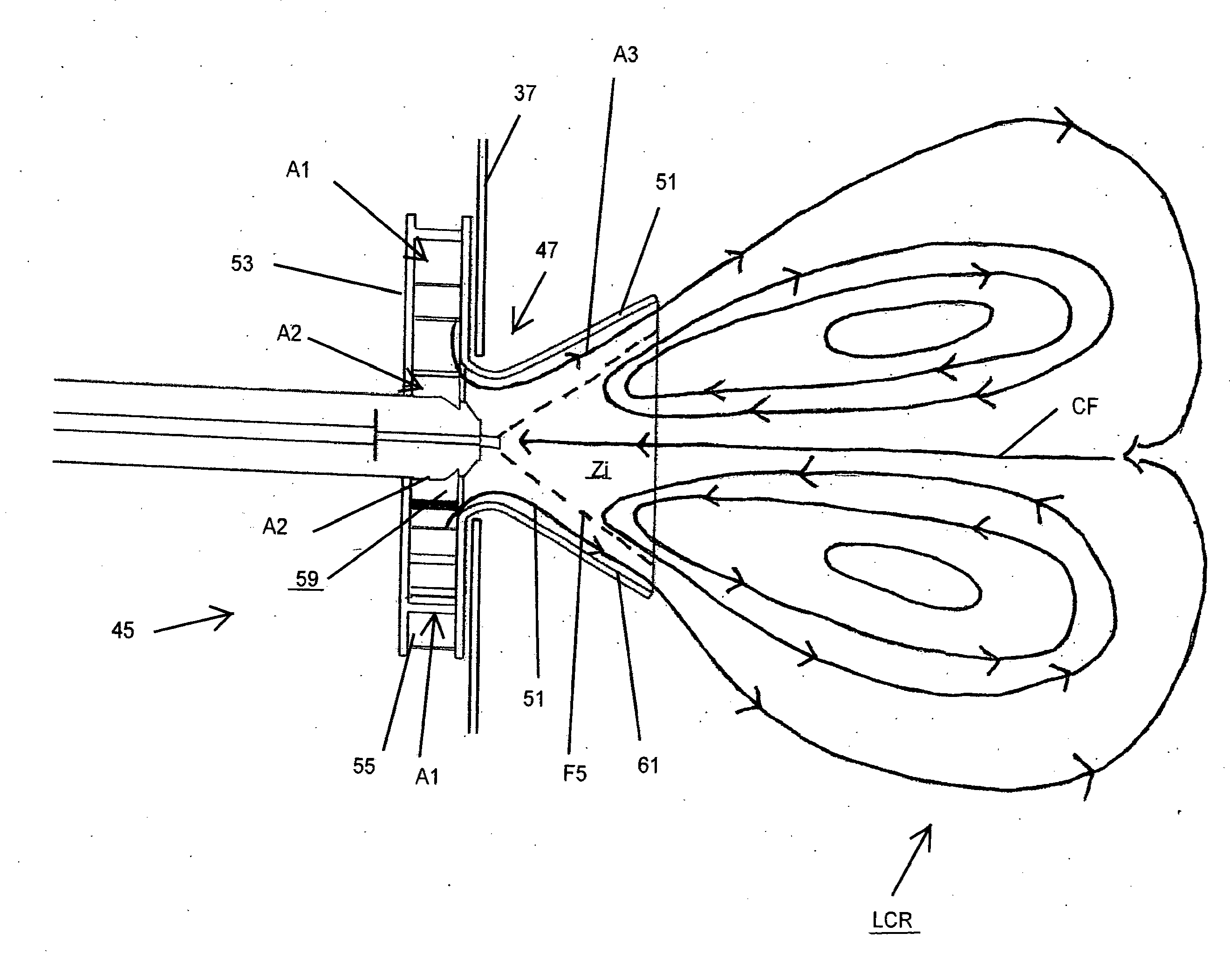
[0020]In the pursuit of desirable combustion properties, including stable and substantially complete fuel burning with low levels of harmful emissions, it is desirable to generate high speed counter flows, and fine scale Karman eddies so as to promote fast and fine mixing of combustion constituents. As further understood by applicants, fast and fine mixing, including preheating, facilitates uniformly volume distributed oxidation and uniform flameless combustion. To achieve these specific conditions, applicants sought to provide a combustor and method that entail the specific organization of advantageous flows preceding or simultaneous with combustion.
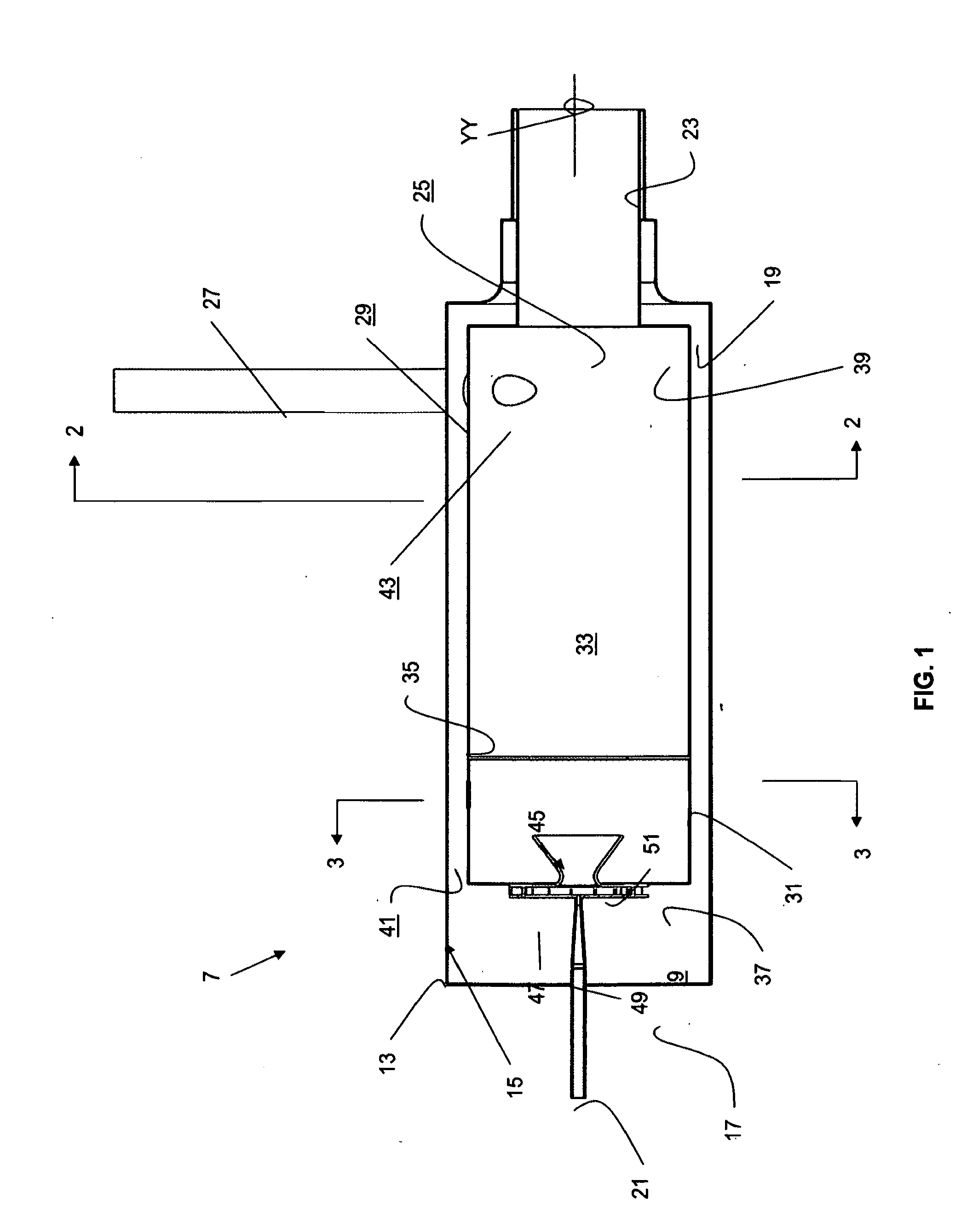
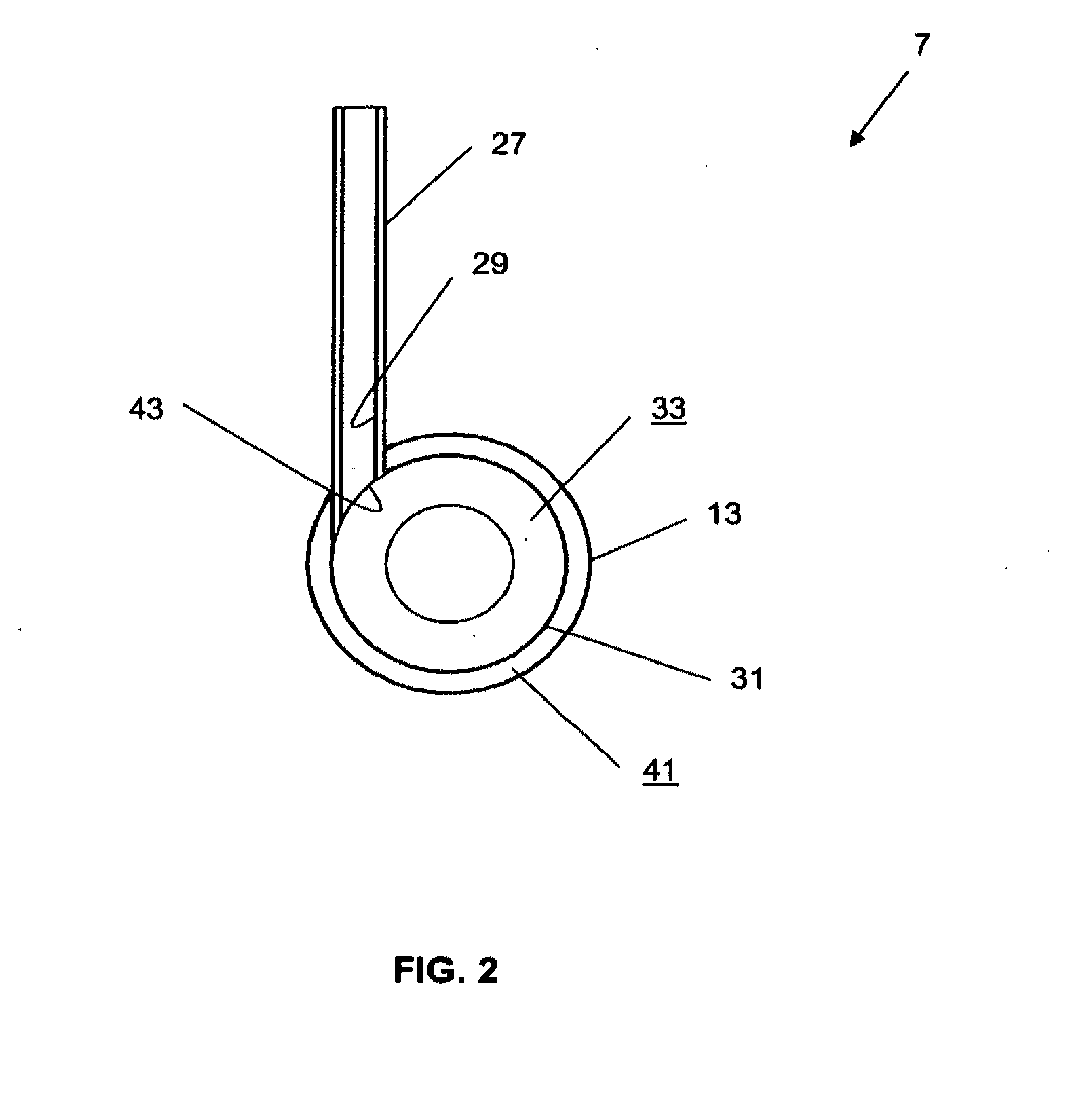
[0021]In one aspect, a combustion apparatus is disclosed having a generally elongated combustion container. The container has a longitudinal axis, a proximal end, an exhaust end spaced axially forward from the proximal end, a proximate end wall, an exhaust end wall, and an all-around sidewall extending between the end walls and about the longitudinal axis, the end walls and sidewall substantially defining a combustion chamber. The apparatus further includes a combustion chamber exhaust positioned on the exhaust end, a delivery system positioned to direct fuel into the combustion chamber for combustion, and an air inlet located generally tangentially on the sidewall to direct air flow generally tangentially into the chamber and induce swirl about the longitudinal axis. In a preferred embodiment, an outside casing is provided about the combustion container and spaced circumferentially outward from the container to define an air annulus therebetween. The casing is equipped with an outer air inlet that communicates an external air supply with both the annulus and the air inlet into the combustor chamber. Accordingly, the air annulus can direct air flow toward the proximate end and along the outside of the container thereby exchanging heat with the side walls of the container and more preferably, directing hot air to the proximate end and in the vicinity of a fuel-air delivery system associated with the combustion chamber. In this way, the annulus serves to cool the side walls and recirculate the heat loss back into the combustion chamber.

Problems solved by technology

Nevertheless, the fuel was totally burnt, and carbon monoxide as well as nitric oxide content of the exhaust was found to be extremely low.
Dilution of the combustion air can reduce the oxygen content of the oxidizer, which decreases temperature fluctuations in the combustion chamber as well as the mean temperature, resulting in low amounts of nitric oxide emission.
Accordingly, rather than being able to sell the glycerol, many companies have to pay for its disposal.

Method used


Image

  • Combustion apparatus and methods
  • Combustion apparatus and methods
  • Combustion apparatus and methods

Examples


Embodiment Construction

[0056]The present invention will now be described more fully with reference to the accompanying drawings, which illustrate the various exemplary embodiments of the present invention. This invention may, however, be embodied in many different forms and should not be construed as limited by the illustrated embodiments set forth herein. Rather, these embodiments are provided so that this disclosure will be thorough as well as complete and will fully convey the scope of the invention to those skilled in the art and the best and preferred modes of practicing the invention.

[0057]FIGS. 1-17 depict various combustion systems, components of combustion systems, and various applications of the combustion systems, embodying or exemplifying one or more aspects of the present invention. In one respect, a combustion apparatus according to the invention and its various applications represent improvements to the vortex combustion chamber and the precombustor and main combustor configurations describ...


PUM


Abstract

A combustion apparatus is described having a generally elongated combustion container with a longitudinal axis, a proximal end, an exhaust end spaced axially forward from the proximal end, a proximal end wall, an exhaust end wall, and an all-around sidewall extending between the end walls and about the longitudinal axis. The end walls and sidewall substantially define a combustion chamber. The apparatus also includes a combustion chamber exhaust positioned on the exhaust end, a fuel-air delivery system positioned to direct fuel into the combustion chamber, and an air inlet located generally tangentially on the sidewall to direct air flow generally tangentially into the chamber and induce swirl about the longitudinal axis.

Description

[0001]The present application claims the benefit of U.S. Provisional Application Ser. No. 61 / 403,290, filed on Sep. 12, 2010 (pending). The disclosure of the previously filed provisional application is hereby incorporated by reference for all purposes and made a part of the present disclosure.[0002]This invention was made with government support under Contract Nos. ONR N00014-10-C-0334 and ONR N00014-09-C-0121 awarded by the Office of Naval Research. The government has certain rights in the invention.BACKGROUND OF THE INVENTION[0003]1. Field of the Invention[0004]The present invention relates generally to a fuel combustion method and an apparatus for performing same. More particularly, the invention relates to an apparatus and / or method for providing a generally uniformly volume distributed combustion, and further, an improved apparatus and / or method of mixing for uniformly volume distributed combustion.[0005]2. Description of Related Art[0006]It was arguably not until the late 1970...

Claims


Application Information

Patent Timeline
IPC IPC(8): F23D14/24F23C6/00F23C5/24F23M9/02F23L15/00
CPCY02E20/342F23L15/00F23C2900/99001F23C7/004F23C99/00F23C3/006Y02E20/34
Inventor BORISSOV, ANATOLISHTERN, VLADIMIR
Owner GENERAL VORTEX ENERGY
Features
  • Generate Ideas
  • Intellectual Property
  • Life Sciences
  • Materials
  • Tech Scout
  • Unparalleled Data Quality
  • Higher Quality Content
  • 60% Fewer Hallucinations
Learn More