Pinned connection system for crane column segments

Active Publication Date: 2012-03-22
MANITOWOC CRANE CO LLC
View PDF29 Cites 18 Cited by
  • Summary
  • Abstract
  • Description
  • Claims
  • Application Information

AI Technical Summary

Benefits of technology

[0010]An improved connection system for crane column segments, such as a boom segments, has been invented. With the invention, boom segments have connectors that include at least one tight fitting pin that can be initially used to hold the boom segments together while other pins, which may have a looser fit, are then inserted to finish the connection. In the preferred embodiment, each connector includes two pins, thus reducing the size of each

Problems solved by technology

Large capacity cranes require very large boom cross sections.
As a result, the pins have a tight fit, further increasing the difficulty in assembling the boom.
Where the crane is moved frequently, the costs to assemble and disassemble the boom may exceed the cost to lift and position the load for which the crane is used.
In add

Method used


Image

  • Pinned connection system for crane column segments
  • Pinned connection system for crane column segments
  • Pinned connection system for crane column segments

Examples


Embodiment Construction

[0030]The present invention will now be further described. In the following passages, different aspects of the invention are defined in more detail. Each aspect so defined may be combined with any other aspect or aspects unless clearly indicated to the contrary. In particular, any feature indicated as being preferred or advantageous may be combined with any other feature or features indicated as being preferred or advantageous.

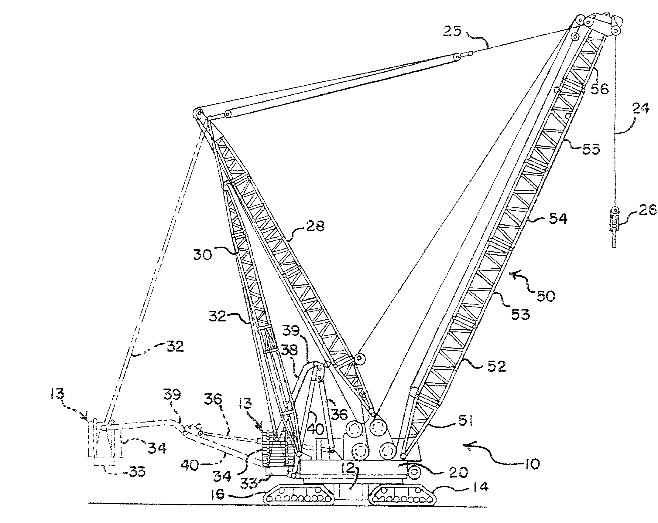
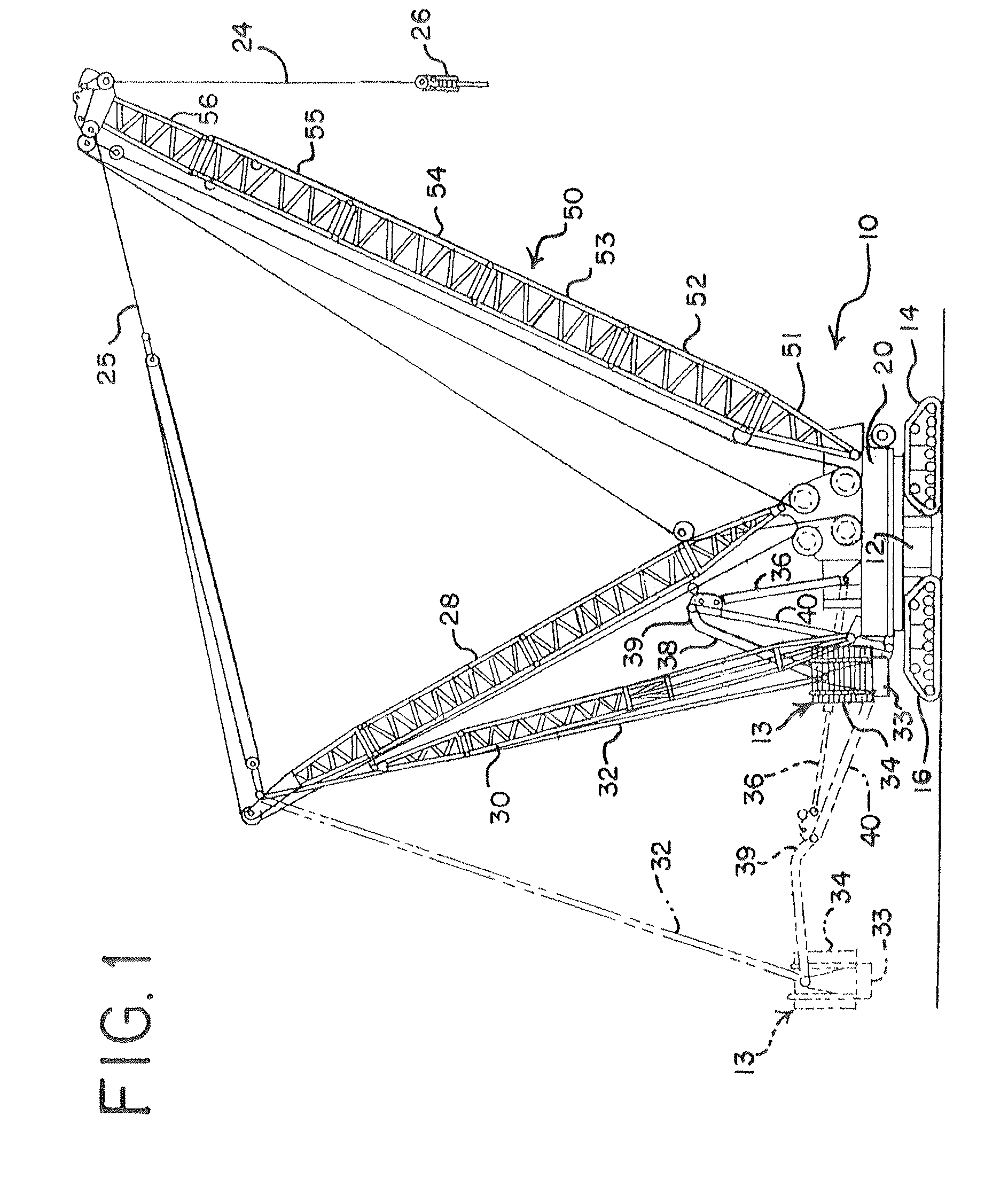
[0031]The preferred embodiment of the present invention relates to a high capacity mobile lift crane, other aspects of which are disclosed in U.S. Pat. No. 7,546,928 (Mobile Lift Crane With Variable Position Counterweight), U.S. Pat. No. 7,762,412 (Mast Raising Structure And Process For High-Capacity Mobile Lift Crane), U.S. Pat. No. 7,946,560 (Crane Hook Block), U.S. Pat. No. 7,954,657 (Connection System For Crane Boom Segments), U.S. Pat. No. 7,967,158 (Mobile Lift Crane With Variable Position Counterweight) and U.S. Pat. No. 7,997,432 (Trunnion Transportati...


PUM

PropertyMeasurementUnit
Lengthaaaaaaaaaa
Lengthaaaaaaaaaa
Diameteraaaaaaaaaa

Abstract

A crane includes first and second column segments. At least a first, third and fifth connector are located on the first segment, respectively mating with at least a second, fourth and sixth connector on the second segment. Each of the connectors includes at least a first extension having a through-hole positioned in the extension such that the through-holes of mating connectors are aligned when the column segments are aligned. A first pin fits tightly through the through-hole of the first extension on the first connector and the through-hole of the first extension on the second connector to hold the first and second connectors together. A second pin fits loosely through the through-hole of the first extension on the third connector and the through-hole of the first extension on the fourth connector to hold the second and fourth connectors together. The connectors also include a compressive load bearing surface.

Description

REFERENCE TO EARLIER FILED APPLICATION[0001]The present application claims the benefit of the filing date under 35 U.S.C. §119(e) of Provisional U.S. Patent Application Ser. No. 61 / 384,709, filed Sep. 20, 2010, which is hereby incorporated by reference in its entirety.BACKGROUND OF THE INVENTION[0002]The present invention relates to lift cranes, and more particularly to connection systems for connecting sectional column members for cranes and the like.[0003]Large capacity lift cranes typically have elongate load supporting column structures, such as the crane boom, mast and jib structure, comprised of sectional column members secured in end-to-end abutting relationship. Predominantly, each of the sectional column members is made of a plurality of chords and lacing or lattice elements. The terminal end portions of each chord are generally provided with connectors of one form or another to secure abutting column segments together and to carry compressive loads between abutting chords....

Claims


Application Information

Patent Timeline
IPC IPC(8): B66C23/70B23P11/00F16B7/00
CPCB66C23/70B66C23/76Y10T403/553Y10T29/49959
Inventor WALKER, ROBERT J.
Owner MANITOWOC CRANE CO LLC
Why Eureka
Try Eureka