Image capturing device

a technology of image capturing and rotating body, which is applied in the field of image capturing devices, can solve the problems of reducing noise, unable to ensure sufficient dependability, and difficult to ensure the repeatability and reproducibility of optical shift amounts, so as to prevent liquid from increasing viscosity and stably rotate the rotation body

Inactive Publication Date: 2012-03-22
PANASONIC CORP
View PDF12 Cites 16 Cited by
  • Summary
  • Abstract
  • Description
  • Claims
  • Application Information

AI Technical Summary

Benefits of technology

[0015]In view of the above circumstances, a main object of the present invention is to provide an image capturing device which is capable of stably rotating a rotation body even in a cold environment.
[0017]In the present invention, the liquid can be heated by the heater via the capsule member. Therefore, it is possible to prevent the liquid from increasing its viscosity even in a low temperature, thereby making it possible to stably rotate the rotation body.

Problems solved by technology

The resolution of the image capturing element is limited because it depends on the size of pixels and the number of pixels in the image capturing element.
However, with the conventional technology disclosed in the Related Arts 2 and 3, the parallel plate is rotationally driven by transmitting a driving force of a motor to the parallel plate through a gear mechanism, therefore it is neither possible to secure sufficient dependability nor to reduce noise.
Thus, it is difficult to ensure a repeatability and reproducibility of an optical shift amount (shift position).
When it is not known, however, a circumstance arises where a large amount of calculation cost is incurred by a repetitive processing.
In a case of using water as a liquid, the water possibly freezes and damages the capsule when a surrounding temperature drops below the freezing point.
In general, however, an anti-freeze solution tends to increase its viscosity in a low temperature.
Therefore, it requires a large amount of electricity to rotate a rotation body when the viscosity of the anti-freeze solution is increased when used in a cold environment.
In a case where the viscosity of the anti-freeze solution becomes extremely high, it is difficult to rotate the rotation body with a desired rotation speed.

Method used


Image

  • Image capturing device
  • Image capturing device
  • Image capturing device

Examples


first embodiment

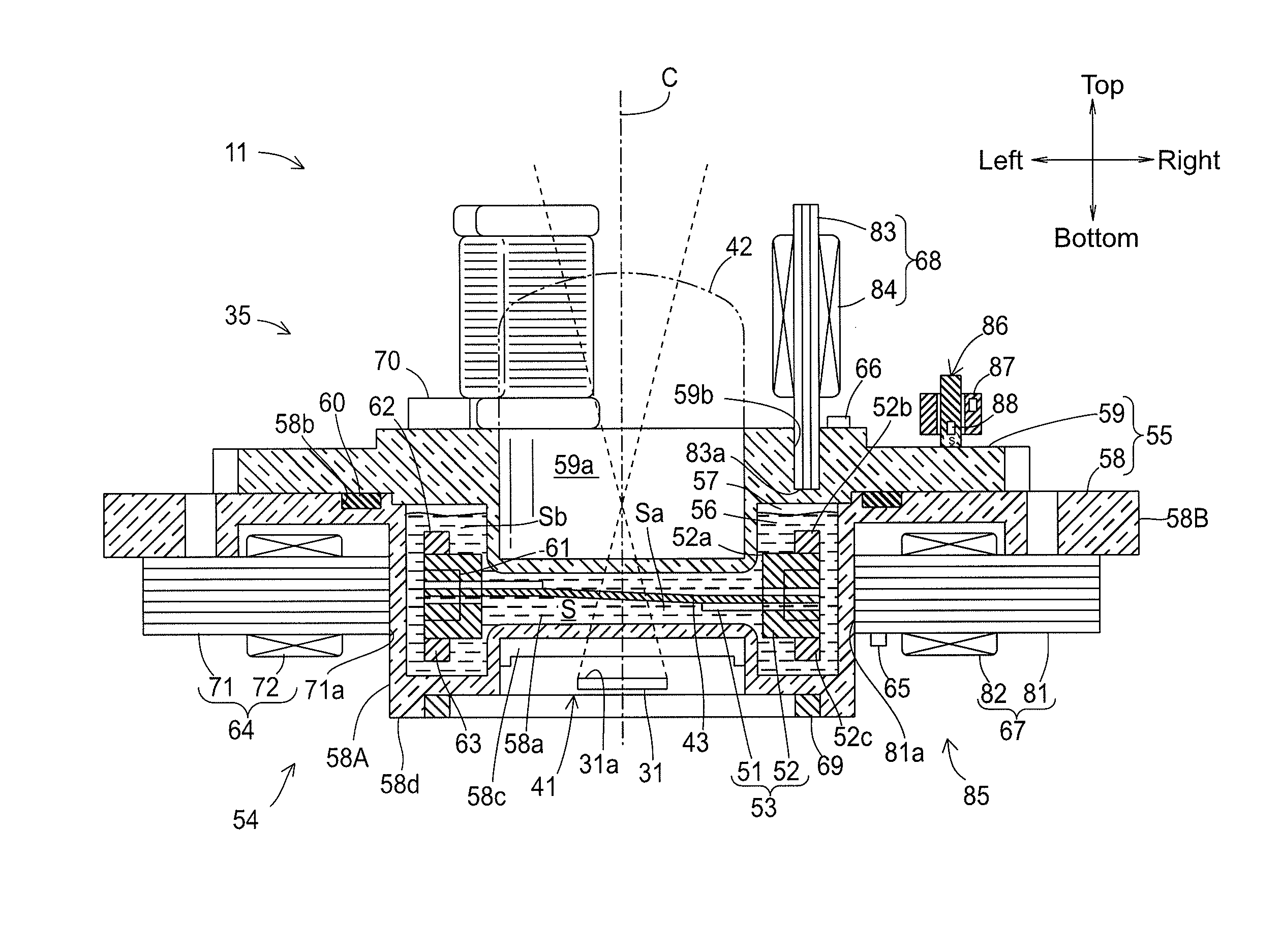
[0042]Hereinafter, a first embodiment of the present invention will be described with reference to the accompanying drawings. In the following description, the “axial” direction refers to the direction of the optical axis (corresponding to the top-bottom direction in FIG. 4), and the “radial” direction refers to the direction perpendicular to the optical axis (corresponding to the left-right direction in FIG. 4). The radial direction can be any angle within 360 degrees around the optical axis.

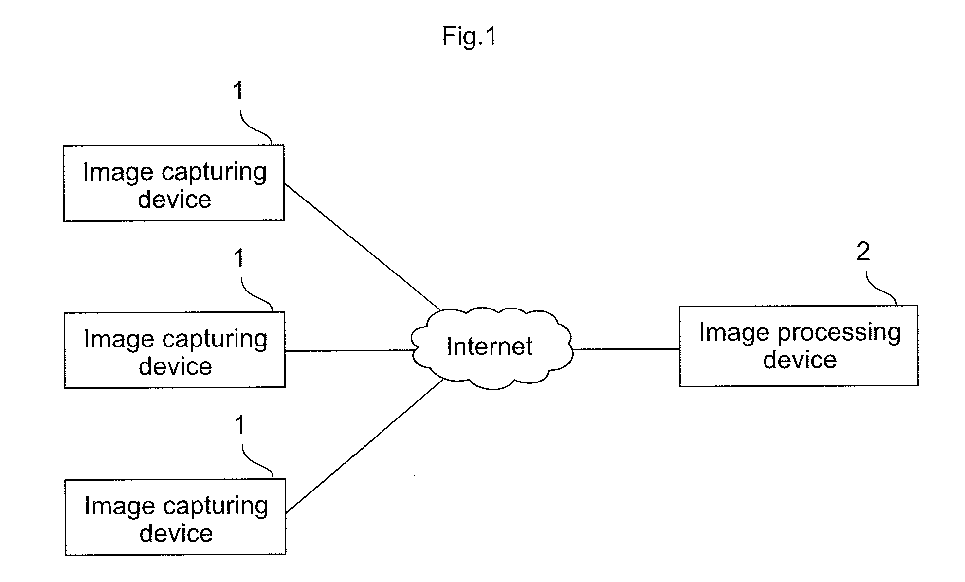
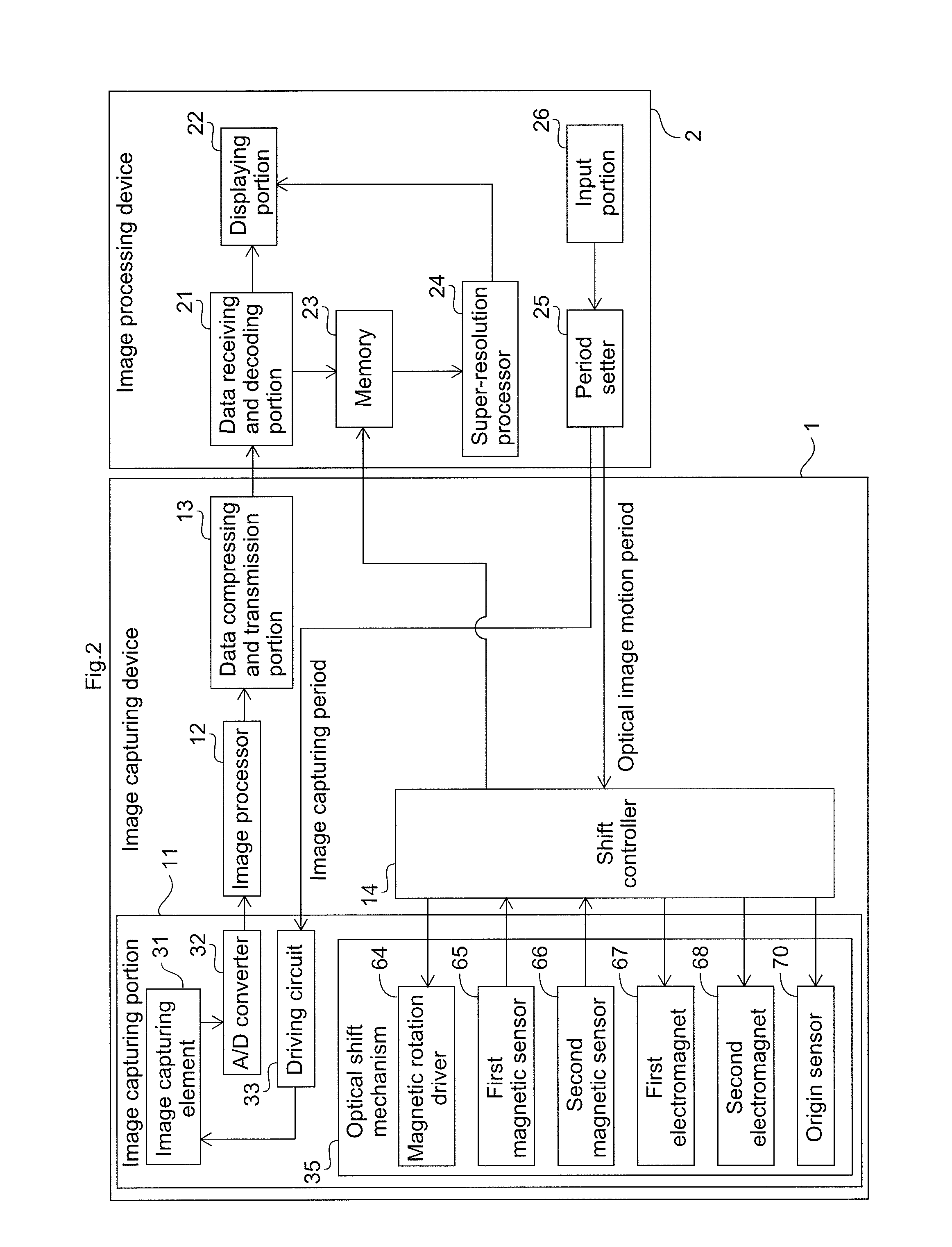
[0043]FIG. 1 illustrates an overall configuration of a network camera system according to the present invention. As shown in FIG. 1, the network camera system to which the present invention is applied includes at least one image capturing device (network camera) 1, and an image processing device (host device) 2. The image capturing device 1 and the image processing device 2 are connected through the Internet, and a captured image data generated by the image capturing device 1 is transmitted to ...

second embodiment

[0163]The first embodiment describes a configuration where a parallel plate is encapsulated with a liquid so that the parallel plate magnetically floats in the liquid. The configuration is further provided with a heater to heat the liquid, thereby making it possible to always provide a stable optical shift amount. When an optical element such as a parallel plate is enclosed in a capsule along with a liquid, in reality, it is difficult to seal the capsule without including any air inside thereof Even when the capsule is manufactured with no air included inside at the time of manufacturing, since the material for a capsule is limited to a transparent resin or the like, volume of the liquid repeatedly changes in a long-term use due to changes in ambient temperature, which may lead to a phenomenon where the outside air passes through the capsule and enters inside thereof Alternatively, it is also possible to purposefully introduce air into the capsule in advance at the time of manufactu...

third embodiment

[0186]FIG. 19 is a schematic plan view of a rotation body 53 according to a third embodiment in the present invention. Herein, only points different from the second embodiment are illustrated. Configuration components similar to the second embodiment are provided with the same numerical references, and illustration thereof is omitted. The same applies to following embodiments.

[0187]In the second embodiment, as shown in FIG. 16A, the through holes 46 are formed in the radial direction of the rotation body 53. In the rotation body 53 of the present embodiment, as shown in FIG. 19, through holes 146 (gas exhaust paths) are provided in such a way that the through holes 146 are more inclined toward the direction opposite to the rotation direction from the radial direction of the rotation body 53 as the through holes 146 get closer to the outer side in the radial direction.

[0188]As described above, in accordance with the rotation of the rotation body 53, the liquid 56 generates a swirling...


PUM


Abstract

A rotation body having an optical member is stored in an optical capsule that is filled with a liquid that is an anti-freeze solution. A magnetic rotation driver rotates the rotation body by applying a magnetic force in a rotation direction to a first magnetizer provided to the rotation body, and heats the liquid. Specifically, the stator core that configures the magnetic rotation driver is formed so that a surface opposing the first magnetizer fits along a curved surface of an outer surface of the optical capsule. The opposing surface is applied with a silicon grease and then firmly attached to the optical capsule. Thus, the entire opposing surface of the stator core acts as a thermal conduction path to more efficiently heat the liquid, thereby making it possible to stably rotate the rotation body even in a cold environment.

Description

CROSS-REFERENCE TO RELATED APPLICATIONS[0001]The present application claims priority under 35 U.S.C. §119 of Japanese Applications No. 2010-208092, filed on Sep. 16, 2010, and No. 2010-219214, filed on Sep. 29, 2010, the disclosures of which are expressly incorporated by reference herein in their entireties.BACKGROUND OF THE INVENTION[0002]1. Field of the Invention[0003]The present invention relates to an image capturing device that obtains a plurality of images by performing image capturing while slightly displacing optical images formed on a light-receiving surface of an image capturing element relative to the image capturing element.[0004]2. Description of Related Art[0005]An image capturing device employs an image capturing element in which pixels are arranged in a two-dimensional matrix pattern. The resolution of the image capturing element is limited because it depends on the size of pixels and the number of pixels in the image capturing element. To generate images having a hi...

Claims


Application Information

Patent Timeline
Patent Type & Authority Applications(United States)
IPC IPC(8): H04N5/225
CPCH04N5/349H04N5/23232H04N23/951H04N25/48
Inventor TOYOMURA, YUUJIURANO, SEIJI
Owner PANASONIC CORP
Why Eureka
Try Eureka