Image processing apparatus, control method thereof, and computer program

a technology of image processing and control method, applied in the field of image processing apparatus, control method thereof, and computer program, can solve the problems of imposing a tremendous load on the user, revealing any method of calculating the layer boundary of a region, and troublesome processing, and achieve the effect of high-precision detection

Inactive Publication Date: 2012-03-22
CANON KK
View PDF4 Cites 32 Cited by
  • Summary
  • Abstract
  • Description
  • Claims
  • Application Information

AI Technical Summary

Benefits of technology

[0008]Hence, the present invention selects types of layers to be detected according to the state of a retina of an eye to be examined, and detects layers based on anatomical features of retina layers, thus allowing high-precision detection of layer boundaries as well as an attenuation region.

Problems solved by technology

When a proper processing result cannot be obtained, the operator has to perform a re-measurement by changing the analysis mode to that suited to another disease and changing image processing parameters, resulting in troublesome processing.
For this reason, large quantities of data are to be analyzed, a tremendous load is imposed on the user.
Furthermore, the method described in Japanese Patent Laid-Open No. 2008-073099 above does not disclose any method of calculating a layer boundary of a region where an artifact is generated.
For this reason, when no signal attenuation occurs on each back-projection region on the tomogram, the layer boundary result becomes inaccurate.
Also, the above method copes with only signal attenuation due to a blood vessel, but it does not cope with any signal attenuation due to morbid portions such as an exudate and bleeding.

Method used


Image

  • Image processing apparatus, control method thereof, and computer program
  • Image processing apparatus, control method thereof, and computer program
  • Image processing apparatus, control method thereof, and computer program

Examples


Embodiment Construction

[0025]The best mode for carrying out the present invention will be described in detail hereinafter with reference to the drawings. However, the scope of the invention is not limited to illustrated examples.

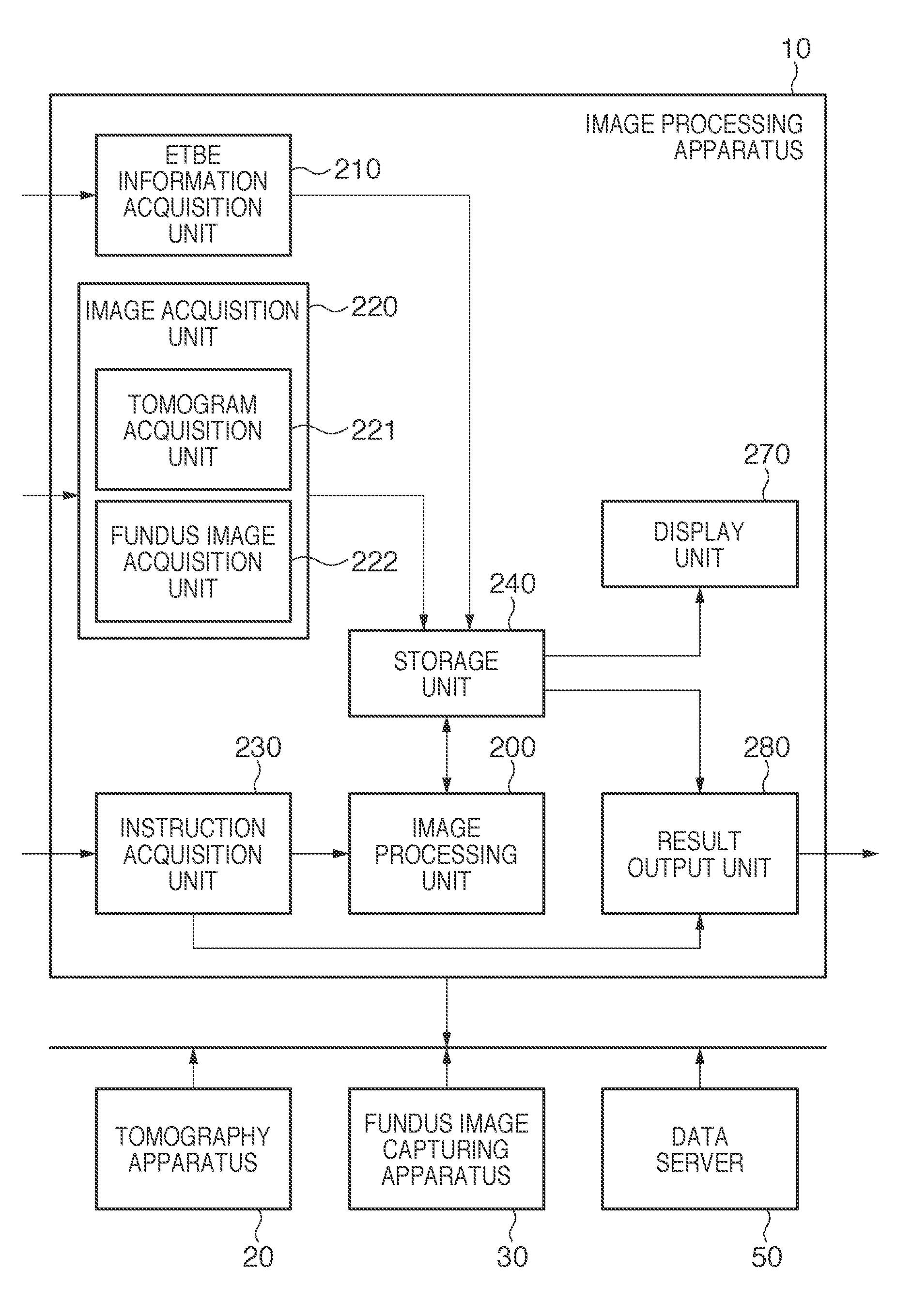
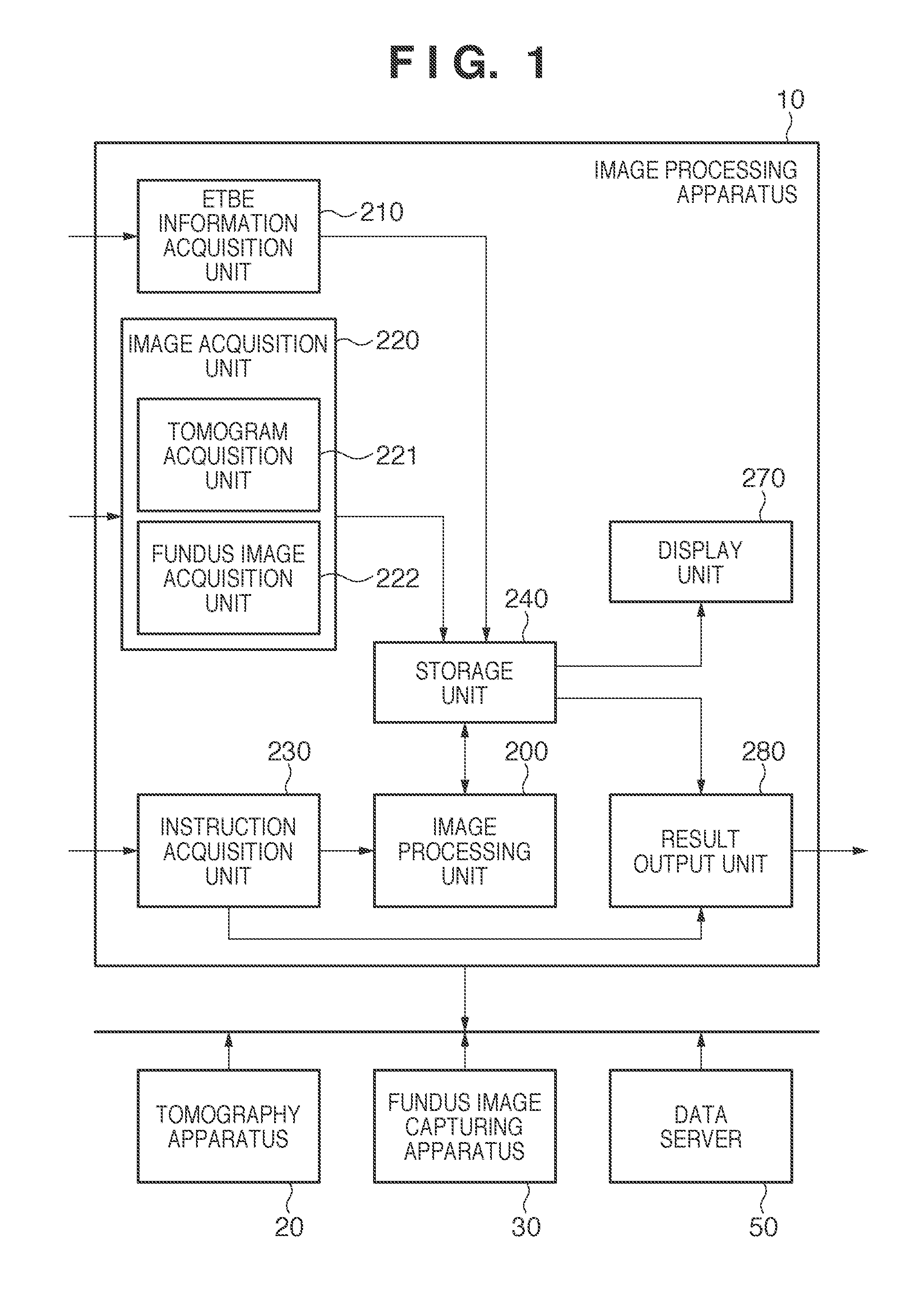
[0026]According to one aspect of an embodiment of the invention, an image processing apparatus 10 acquires a tomogram and fundus image of an eye to be examined, and generates a projection image from the tomogram so as to perform registration between the tomogram and fundus image. Then, the apparatus 10 detects anatomical information required to determine the presence / absence and type of a disease from the fundus image and projection image, determines layers to be measured based on the detection result, and executes analysis processing of predetermined layers. Note that this embodiment will explain a tomogram in which a macula portion appears. However, a portion to be captured is not limited to a macula portion, but the same processing may be applied to an optic papilla. Furthermor...


PUM


Abstract

An image processing apparatus, which analyzes retina layers of an eye to be examined, comprising, means for extracting a feature amount, which represents an anatomical feature in the eye to be examined, from a projection image obtained from a tomogram of the retina layers and a fundus image of the eye to be examined, means for determining a type of the anatomical feature based on the feature amount, means for deciding layers to be detected from the retina layers according to the determined type of the anatomical feature, and detecting structures of the decided layers in the tomogram, and means for modifying the structure of the layer included in a region having the anatomical feature of the structures of the layers detected by the layer structure detection means.

Description

TECHNICAL FIELD[0001]The present invention relates to an image processing apparatus, control method thereof, and computer program.BACKGROUND ART[0002]Ophthalmic examinations are commonly made for the early diagnosis of various diseases that come before lifestyle-related diseases and causes of blindness. Since a medical examination or the like is required to find a disease in a whole eye portion, an examination using an image over a broad range of the eye portion (to be referred to as a fundus image hereinafter) is indispensable. The fundus image is captured using a fundus camera or SLO (Scanning Laser Opthalmoscope). On the other hand, a tomography apparatus for an eye portion such as an OCT (Optical Coherence Tomography) is expected to effectively give more adequate diagnoses of diseases since it allows to three-dimensionally observe the state of the interior of retina layers.[0003]FIG. 5A is a pattern diagram of a macula tomogram of a retina captured by the OCT. A tomogram of an e...

Claims


Application Information

Patent Timeline
Patent Type & Authority Applications(United States)
IPC IPC(8): G06K9/00
CPCG01N21/4795G06T2207/10101G06T7/602G06T7/0012G06T7/0083G06T2207/30041G06T7/12G06T7/62A61B3/10A61B3/12G01N21/17
Inventor IWASE, YOSHIHIKOIMAMURA, HIROSHIFURUKAWA, DAISUKE
Owner CANON KK
Why Eureka
Try Eureka