
Propeller and system of counter-rotating propellers comprising improved means for limiting pitch, and a turbine engine comprising them

Active Publication Date: 2012-03-22
SN DETUDE & DE CONSTR DE MOTEURS DAVIATION S N E C M A
View PDF2 Cites 4 Cited by
  • Summary
  • Abstract
  • Description
  • Claims
  • Application Information

AI Technical Summary

Benefits of technology

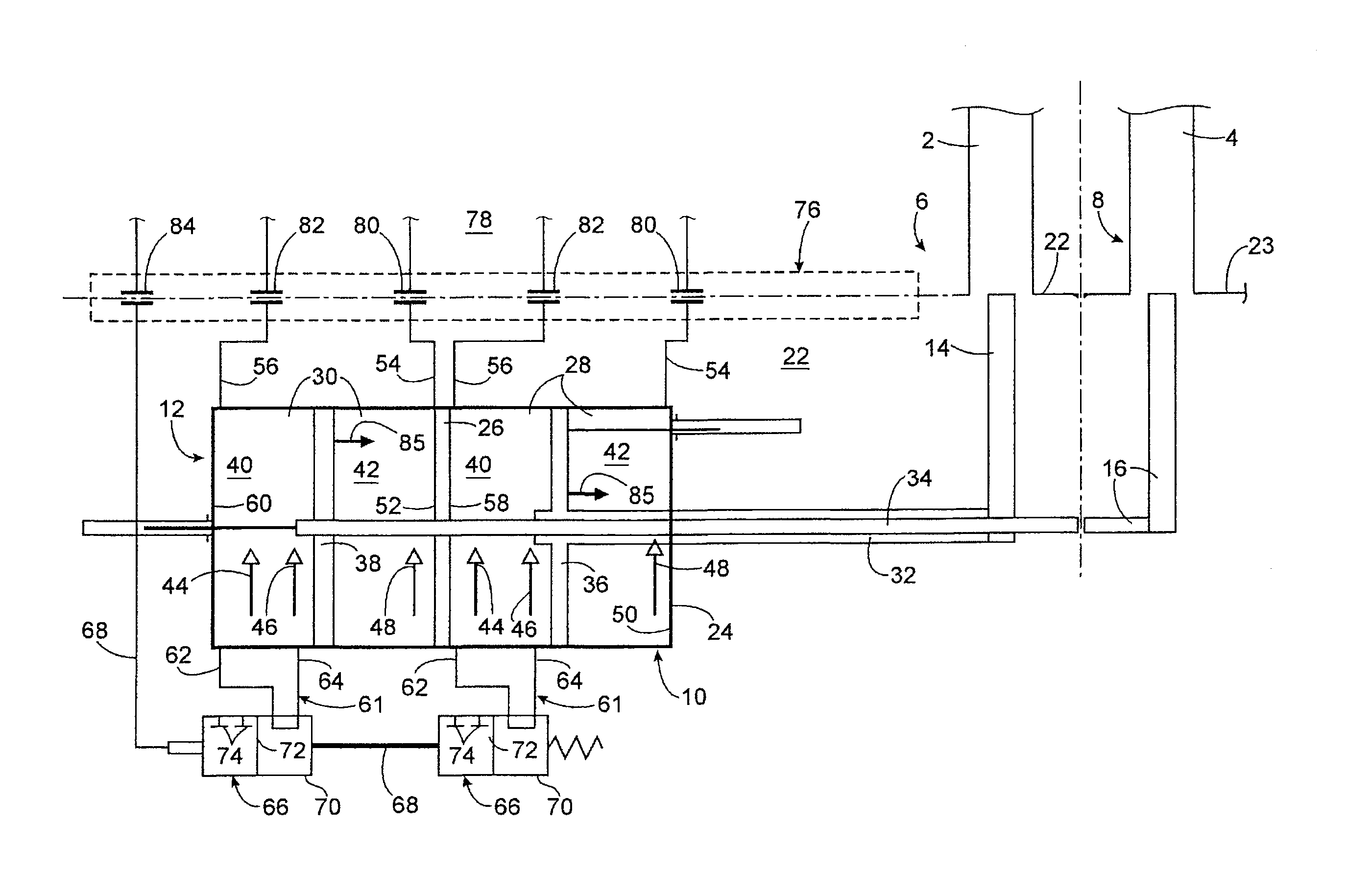
[0014]By having both chambers defined on either side of each piston of each actuator communicate, it is possible to ensure fluid pressure equality in both of these chambers and thereby interrupt any displacement of the piston tending to move the blades in said predetermined direction beyond said predetermined limiting pitch angle.
[0047]This configuration is particularly advantageous because it allows a hydraulic route to be saved relatively to a configuration in which the hydraulic connection means would be borne by the stator, and the transfer bearing of which would have to include two pairs of hydraulic routes respectively dedicated to the control of the actuators of each propeller as well as at least two additional hydraulic routes respectively corresponding to the second respective portions of the hydraulic circuits of said hydraulic connection means associated with both propellers.

Problems solved by technology

However, involuntary adjustment of the blades of a propeller on a position of small pitches or thrust-inversion, corresponding to a low or negative pitch angle, may cause serious problems when it occurs in certain flight phases.
Now, such an involuntary adjustment may result from a pilot error but also from a failure of the members for controlling the pitch pitch of the blades of the propellers.
However, because of their mechanical nature, these means have limited reliability, notably liable to induce maintenance overcosts.
This is in particular a penalty in the case of systems of counter-rotating propellers, which include two propellers and therefore two safety devices of the type described above.

Method used


Image

  • Propeller and system of counter-rotating propellers comprising improved means for limiting pitch, and a turbine engine comprising them
  • Propeller and system of counter-rotating propellers comprising improved means for limiting pitch, and a turbine engine comprising them

Examples


Embodiment Construction

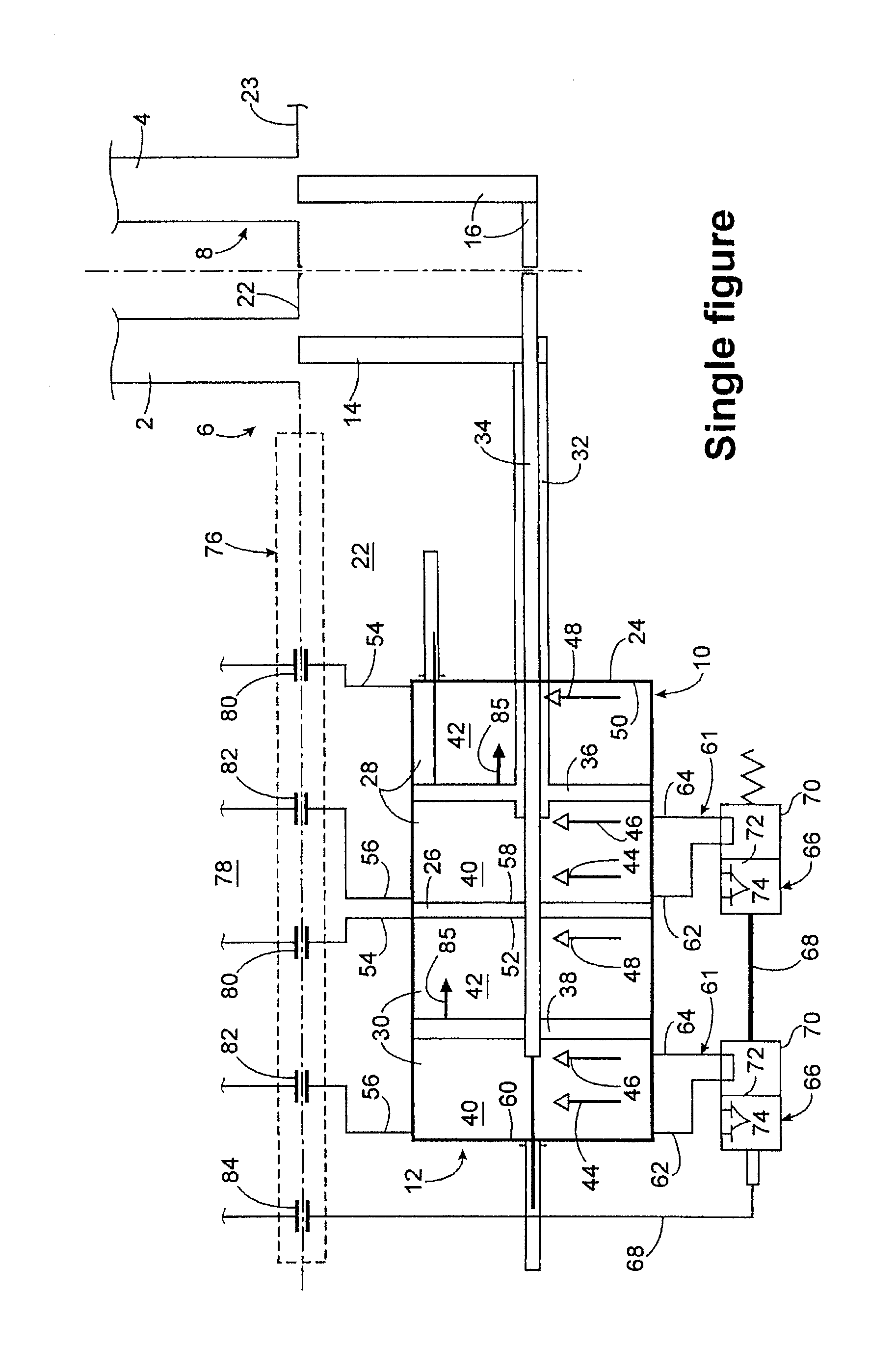
[0056]The single FIGURE very schematically illustrates a system of counter-rotating propellers in an airplane turbine engine according to the invention and more particularly represents adjustment means for controlling the pitch of the blades 2, 4 of both propellers 6 and 8 of this counter-rotating propeller system.

[0057]These adjustment means notably comprise two double acting hydraulic cylinders or actuators 10 and 12 respectively intended for adjusting the pitch of the blades of both aforementioned propellers 6 and 8.

[0058]A first actuator 10 is intended for adjusting the pitch of the blades 2 of a first propeller 6 of this system of counter-rotating propellers via mechanical connection means 14 between this first actuator 10 and the blades 2 of the first propeller 6. This first actuator 10 as well as these mechanical connection means 14 are borne by the rotor 22 of the first propeller 6.

[0059]A second actuator 12 is intended for the adjustment of the pitch of the blades 4 of a se...


PUM


Abstract

A propeller for an aircraft turbine engine, comprising means for adjusting the pitch of the blades comprising a hydraulic actuator borne by the rotor and including a cavity and a piston displaceable in said cavity and dividing said cavity into two chambers, as well as means for limiting the stroke of the piston in order to prevent displacement of said blades in a predetermined direction beyond a predetermined limiting pitch angle, and comprising hydraulic connection means with which both chambers may be put into communication with each other as soon as the pitch angle of the blades becomes equal to said predetermined limiting pitch angle during the displacement of said blades in said predetermined direction, these hydraulic connection means being borne by said rotor of the propeller.

Description

TECHNICAL FIELD[0001]The present invention relates to the field of aircraft turbine engines and more particularly to the adjustment of the pitch of the blades of one or more propellers in an aircraft turbine engine, such as an airplane turbo-prop or turbojet engine.[0002]The invention may notably be applied to turbine engines equipped with a system of counter-rotating propellers and in particular to so called “open rotor” turbine engines, the propellers of which are without any fairing at their external radial ends.STATE OF THE PRIOR ART[0003]It is well known how to equip propellers of aircraft turbine engines with means for adjusting the pitch of the blades of these propellers in order to adapt said pitch to the different flight conditions of aircrafts. These adjustment means may further allow feathering of the propellers or further a negative pitch allowing these propellers to operate in a thrust-inversion also called reverse mode.[0004]The aforementioned adjustment means usually ...

Claims


Application Information

Patent Timeline
IPC IPC(8): B64C11/38B64C11/48
CPCB64C11/385Y02T50/66B64D2027/026Y02T50/60B64D27/026
Inventor MARLY, PASCAL
Owner SN DETUDE & DE CONSTR DE MOTEURS DAVIATION S N E C M A
Learn More