Unlock instant, AI-driven research and patent intelligence for your innovation.
Battery and ultrasonic bonding method for battery
Active Publication Date: 2012-03-22
KK TOSHIBA
View PDF1 Cites 21 Cited by
Summary
Abstract
Description
Claims
Application Information
AI Technical Summary
This helps you quickly interpret patents by identifying the three key elements:
Problems solved by technology
Method used
Benefits of technology
Benefits of technology
[0011]An objective of the present invention is to provide a battery and an ultrasonic bonding method for a battery that are capable of achieving a reduction in an electric resistance of a lead and securing an excellent bonding strength, by employing ultrasonic bonding.
Problems solved by technology
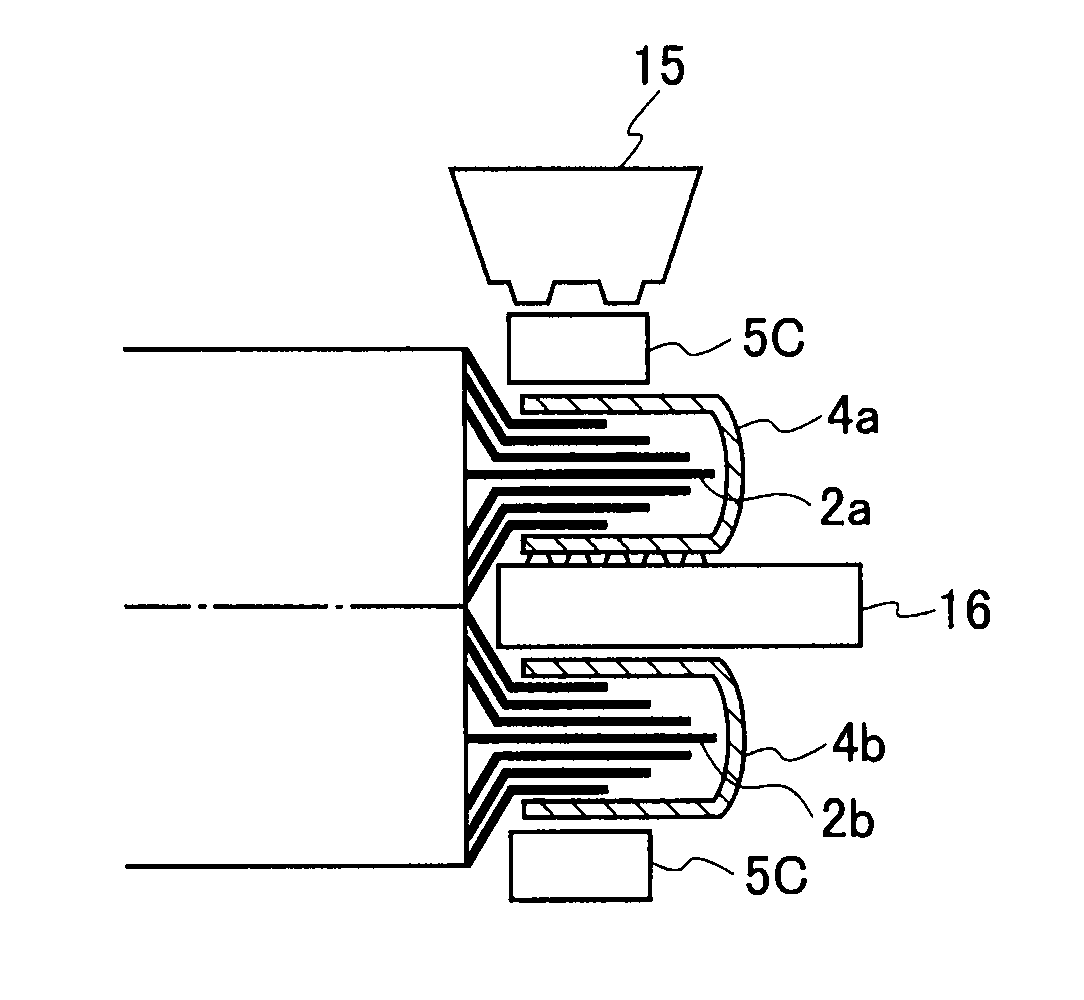
Accordingly, it becomes difficult for the ultrasonic vibration required for the bonding to be transmitted.
As a result, the lead 5 and the metal foils of the current collecting tabs 2a, 2b are not sufficiently bonded, making it difficult to secure a required bond strength.
However, there is a concern that the separator may be damaged by the heat of the laser at a portion bonded by the laser.
For this reason, the output of the laser cannot be increased, and therefore, the required bond strength may not be secured.
Method used
Image
Click on the blue label to locate the original text in one second.
Reading with bidirectional positioning of images and text.
Examples
first embodiment
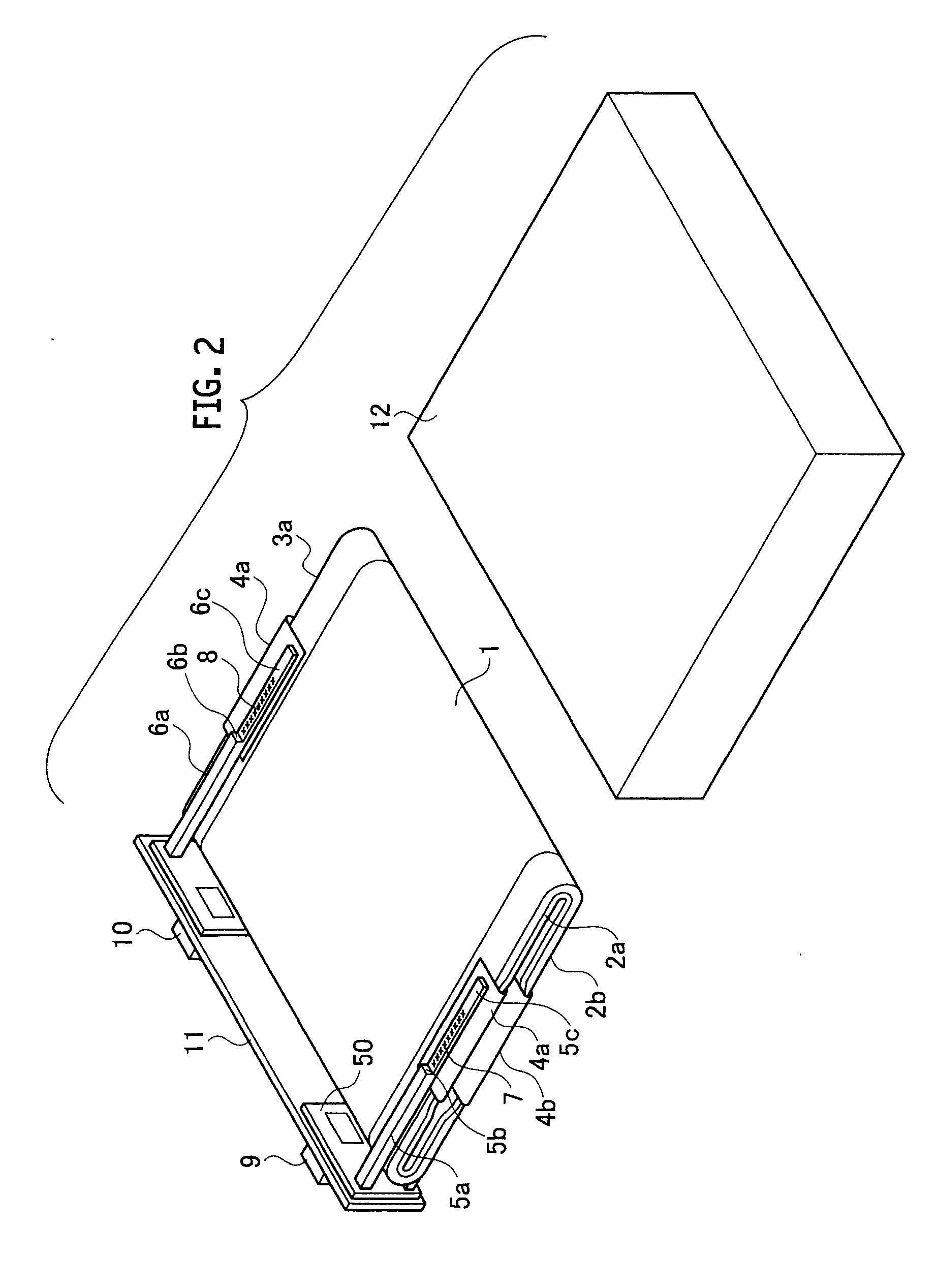
[0022]FIG. 2 is a perspective view illustrating a configuration of a battery according to a first embodiment of the present invention. FIG. 3 is a perspective view of the vicinity of a portion where a positive-electrode lead is connected to positive-electrode current collecting tabs, of the battery according to the first embodiment. The battery illustrated in FIG. 2 is a battery using a non-aqueous electrolyte, and includes a container 12, multiple current collecting tabs 2a, 2b (3a, 3b), leads 5a to 5c (6a to 6c), a lid 11, and external terminals 9 (10). The current collecting tabs 2a, 2b (3a, 3b) are each extended from a positive electrode or a negative electrode of an electrode group 1 including the positive electrode and the negative electrode, and are overlapped with each other. The leads 5a to 5c (6a to 6c) are each bonded to at least one of the current collecting tabs 2a, 2b (3a, 3b) by ultrasonic bonding. The lid 11 is configured to close an opening portion of the container ...
second embodiment
[0037]FIG. 6 is a perspective view of the vicinity of a portion where a positive-electrode lead 5a, 5c, and 5d having a cross-sectional area increased gradually is connected to a positive-electrode current collecting tab 2a, 2b, of a battery according to a second embodiment. In the second embodiment illustrated in FIG. 6, the lead includes a thick lead 5a, a thin lead 5c, and a tapered portion 5d having a cross-sectional area gradually increasing from the lead 5c to the lead 5a.
[0038]Even with the battery according to the second embodiment as described above, since the cross-sectional area is increased gradually from the lead 5c to the lead 5a with the tapered portion 5d, the same effects can be achieved as those of the battery according to the first embodiment.
third embodiment
[0039]FIG. 7 is a perspective view of the vicinity of a portion where a positive-electrode lead having a curved surface in a portion with a cross-sectional area changed is connected to a positive-electrode current collecting tab, of a battery according to a third embodiment. In the third embodiment illustrated in FIG. 7, the lead includes a thick lead 5a, a thin lead 5c, and a curved surface portion 5e having a cross-sectional area increasing from the lead 5c to the lead 5a.
[0040]Even with the battery according to the third embodiment as described above, since the cross-sectional area is increased from the lead 5c to the lead 5a with the curved surface portion 5e, the same effects can be achieved as those of the battery according to the first embodiment.
[0041]As described above, the batteries according to the first to third embodiments make it possible to perform the ultrasonic bonding of the current collecting tab and the lead at a portion having a small cross-sectional area, and ...
PUM
Property
Measurement
Unit
Area
aaaaa
aaaaa
Abstract
The present invention provides a battery including a container, an electrode group including a positive electrode and a negative electrode, multiple current collecting tabs being extended from any one of the positive electrode and the negative electrode of the electrode group, and overlapped with one another; a lead bonded to at least one of the current collecting tabs by ultrasonic bonding, a lid configured to close an opening portion of the container, and an external terminal provided on the lid and connected to the at least one current collecting tab via the lead, in which the lead has a cross-sectional area that is increased in a middle of extension of the lead from an ultrasonic-bonded portion to the at least one of the current collecting tabs to the external terminal.
Description
TECHNICAL FIELD[0001]The present invention relates to a battery, such as a secondary battery, and an ultrasonic bonding method for a battery, and more particularly relates to a technology for a non-aqueous electrolyte secondary battery.BACKGROUND ART[0002]In recent years, non-aqueous electrolyte secondary batteries have been developed, which are capable of fast charge and high power discharge as well as have an excellent cyclic performance. Such non-aqueous electrolyte secondary batteries are thus suitable as vehicle secondary batteries to be mounted on hybrid vehicles and electric vehicles and as power storage secondary batteries used for electric power leveling.[0003]The secondary battery as described above has a structure in which an electrode group and an electrolyte solution impregnated in the electrode group are housed in a battery container as described in Japanese Patent Application Publication No. 2009-26490. In the structure, the electrode group is formed by winding up a s...
Claims
Application Information
Patent Timeline
Application Date:The date an application was filed.
Publication Date:The date a patent or application was officially published.
First Publication Date:The earliest publication date of a patent with the same application number.
Issue Date:Publication date of the patent grant document.
PCT Entry Date:The Entry date of PCT National Phase.
Estimated Expiry Date:The statutory expiry date of a patent right according to the Patent Law, and it is the longest term of protection that the patent right can achieve without the termination of the patent right due to other reasons(Term extension factor has been taken into account ).
Invalid Date:Actual expiry date is based on effective date or publication date of legal transaction data of invalid patent.

