Ultrasound diagnostic apparatus

Inactive Publication Date: 2012-03-22
FUJIFILM CORP
View PDF5 Cites 29 Cited by
  • Summary
  • Abstract
  • Description
  • Claims
  • Application Information

AI Technical Summary

Benefits of technology

[0007]An object of the present invention is to provide an ultrasound diagnostic apparatus in which a plu

Problems solved by technology

Such ultrasound diagnostic apparatus are required reduction in size to pursue ease of operation and convenience, which necessitates reduction of scale of transmission/reception circuits, necessarily resulting in a reduced image quality.
Even equipment comprising a plurality of portable ultrasound diagnostic apparatus each having only small-scale ultrasound transmission/reception ci

Method used


Image

  • Ultrasound diagnostic apparatus
  • Ultrasound diagnostic apparatus
  • Ultrasound diagnostic apparatus

Examples


embodiment 1

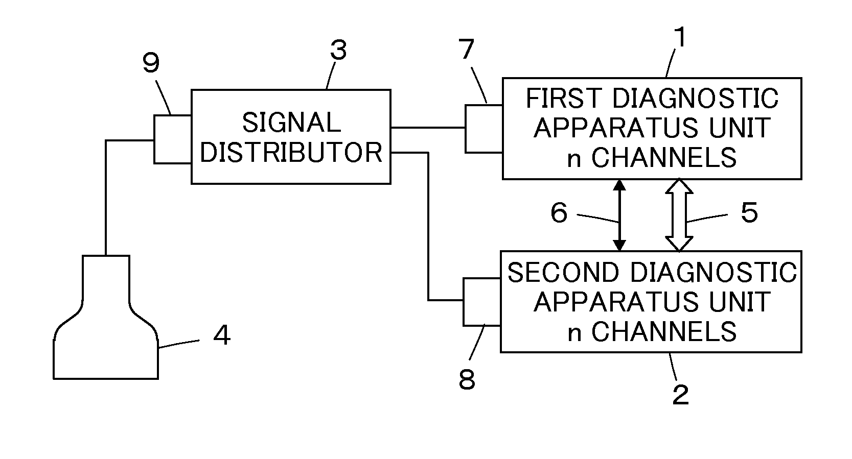
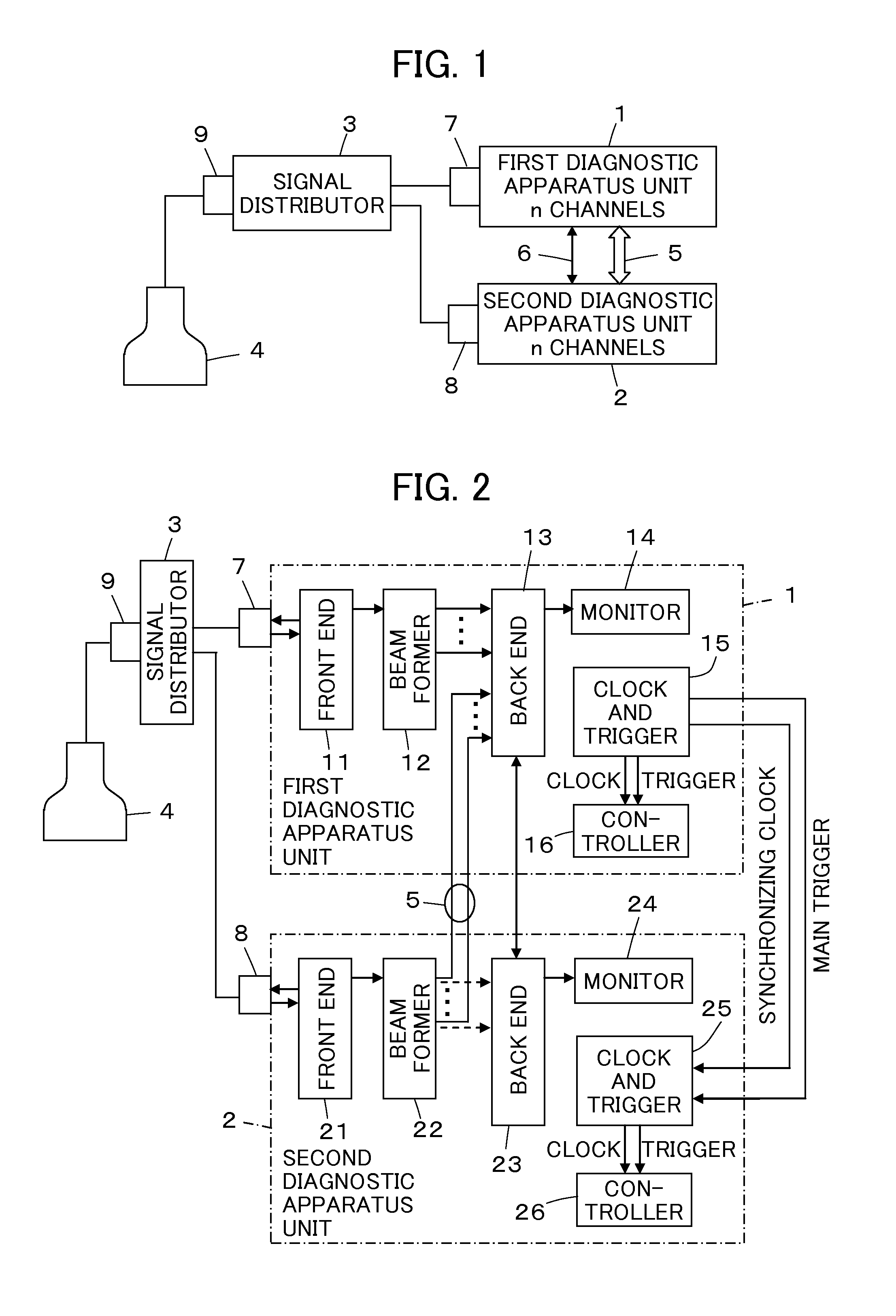
[0033]FIG. 1 illustrates a configuration of an ultrasound diagnostic apparatus according to Embodiment 1 of the invention. The ultrasound diagnostic apparatus comprises a first diagnostic apparatus unit 1 and a second diagnostic apparatus unit 2 as two diagnostic apparatus bodies. These first diagnostic apparatus unit 1 and the second diagnostic apparatus unit 2 are connected via a signal distributor 3 to a common ultrasound probe 4.

[0034]The first diagnostic apparatus unit 1 and the second diagnostic apparatus unit 2 have an identical inner configuration to each other, each comprising n number of channels of ultrasound transmission / reception circuits, and are connected to each other via a data bus 5 and an operation control cable 6.

[0035]The ultrasound probe 4 comprises a transducer array having a number of apertures that is equal to or greater than 2 n, which is the sum of the numbers of channels of the diagnostic apparatus units 1 and 2.

[0036]The signal distributor 3 is connected...

embodiment 2

[0071]Although, according to Embodiment 1, the first diagnostic apparatus unit 1 and the second diagnostic apparatus unit 2, provided respectively with the back ends 13 and 23 for producing the image signal and the monitors 14 and 24 for displaying the ultrasound image, respectively, perform synchronized operation, the invention is not limited thereto; diagnostic apparatus sub-units not provided with any means for producing the ultrasound image may be used as diagnostic apparatus bodies and connected to a common ultrasound probe to achieve synchronized operation.

[0072]FIG. 11 illustrates a configuration of the ultrasound diagnostic apparatus according to Embodiment 2. This ultrasound diagnostic apparatus comprises a first diagnostic apparatus sub-unit 31 and a second diagnostic apparatus sub-unit 32 as two diagnostic apparatus bodies. These first diagnostic apparatus sub-unit 31 and the second diagnostic apparatus sub-unit 32 are connected via the signal distributor 3 to a common ul...

embodiment 3

[0095]FIG. 15 illustrates a specific configuration of the ultrasound diagnostic apparatus according to Embodiment 3. As compared with the apparatus according to Embodiment 2 illustrated in FIG. 12, the ultrasound diagnostic apparatus shown in FIG. 15 additionally comprises a delay estimating unit 51 connected between the diagnostic apparatus sub-units 41-1 to 41-N and the secondary beam former 42 and further differs in that the reception signal from one transducer of the ultrasound probe 4 is inputted via the signal distributor 3 as identical signal Ss to the diagnostic apparatus sub-units 41-1 to 41-N under the control of the controller 47.

[0096]The delay estimating unit 51 estimates the clock skew occurring among the diagnostic apparatus sub-units 41-1 to 41-N based on the processing results yielded by the diagnostic apparatus sub-units 41-1 to 41-N when the identical signal Ss is inputted to the diagnostic apparatus sub-units 41-1 to 41-N, i.e., based on the sound ray signals pro...


PUM


Abstract

An ultrasound diagnostic apparatus comprises: an ultrasound probe including a transducer array; a plurality of diagnostic apparatus bodies corresponding to a plurality of parts of the transducer array for transmitting ultrasonic waves through corresponding transducers and processing reception signals from the corresponding transducers, respectively; and a synchronizing signal supply unit for supplying a common clock signal and a common trigger signal to the plurality of diagnostic apparatus bodies for causing the plurality of diagnostic apparatus bodies to operate in synchronism.

Description

BACKGROUND OF THE INVENTION[0001]The present invention relates to an ultrasound diagnostic apparatus and particularly to a plurality of ultrasound diagnostic apparatus bodies operated in parallel whereby ultrasonic wave transmission and reception are performed from a single ultrasound probe.[0002]Conventionally, ultrasound diagnostic apparatus using ultrasound images have been put to use in the medical field. In general, this type of ultrasound diagnostic apparatus comprises an ultrasound probe equipped with a built-in transducer array and an apparatus body connected to the ultrasound probe. The ultrasound probe transmits ultrasonic waves toward a subject, receives the ultrasonic echoes from the subject, and the apparatus body electrically processes the reception signals to generate an ultrasound image.[0003]In recent years, there have been developed ultrasound diagnostic apparatus of portable type that may be transported to a bed side or to a site where emergency medical care is ne...

Claims


Application Information

Patent Timeline
IPC IPC(8): A61B8/00
CPCA61B8/00G01S7/52082G01S15/8915A61B8/54A61B8/4444A61B8/4483
Inventor SATO, TOMOO
Owner FUJIFILM CORP
Why Eureka
Try Eureka