Electronic device

a technology of electronic devices and control circuits, applied in pulse generators, emergency protective arrangements for limiting excess voltage/current, pulse techniques, etc., can solve problems such as thermal destruction of devices, inability to control circuits, and abnormal sta

Active Publication Date: 2012-03-29
DENSO CORP
View PDF2 Cites 53 Cited by
  • Summary
  • Abstract
  • Description
  • Claims
  • Application Information

AI Technical Summary

Benefits of technology

[0012]With this configuration, it is possible to detect an abnormal state such that the first switching element is unable to be turned off in spite of the drive signal instructing turn-off of the first switching element.

Problems solved by technology

In the above disclosed power converter, in the presence of a fault in the IGBT and / or MOSFETs, it is likely that an abnormal state will occur such that the control circuit is unable to turn off the IGBT in spite of the drive signal instructing the control circuit to turn off the IGBT.
Continuation of such an abnormal state may lead to heat generation in the IGBT, which in turn may lead to thermal destruction of the device.

Method used


Image

  • Electronic device
  • Electronic device
  • Electronic device

Examples


first embodiment

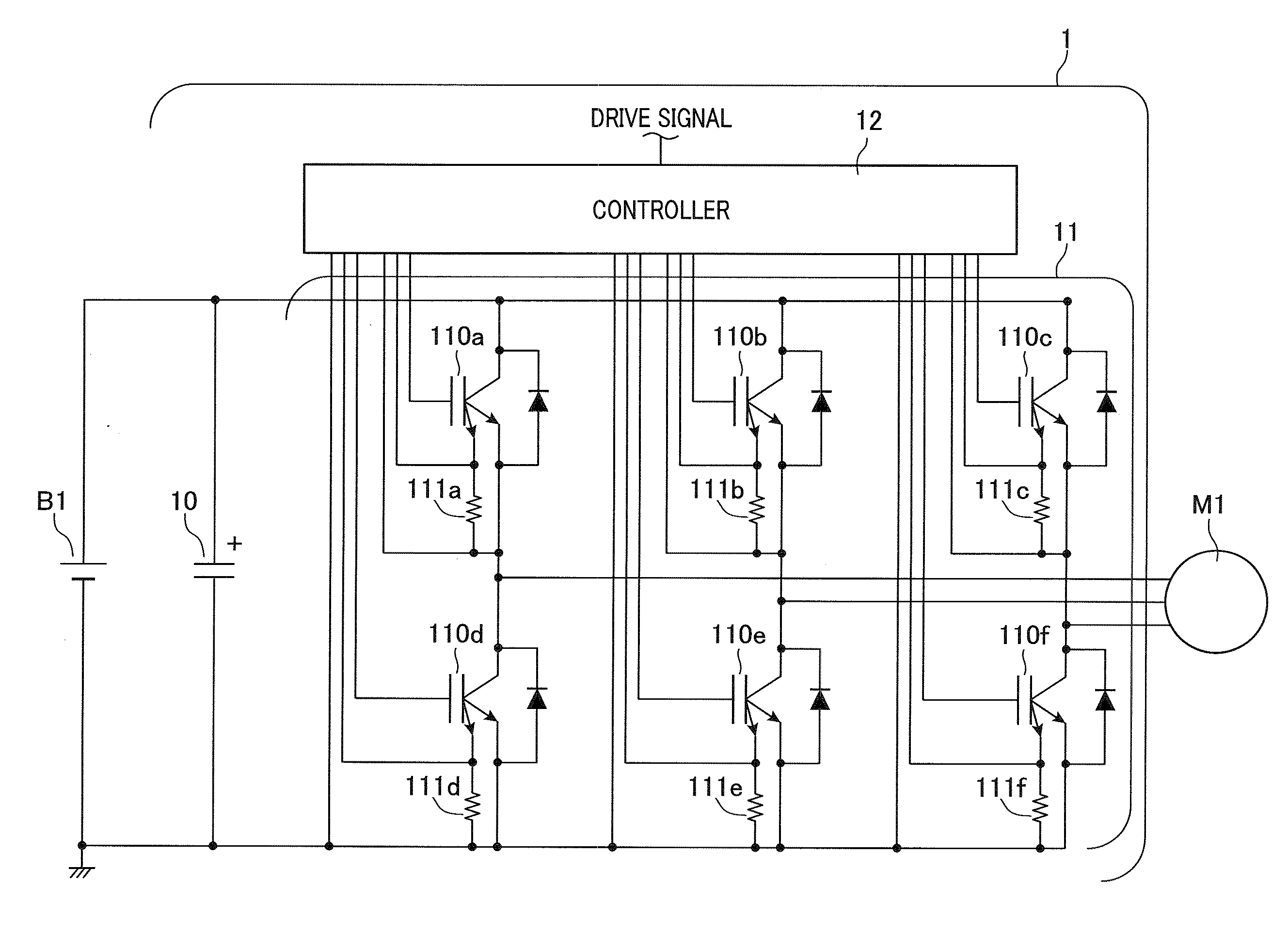
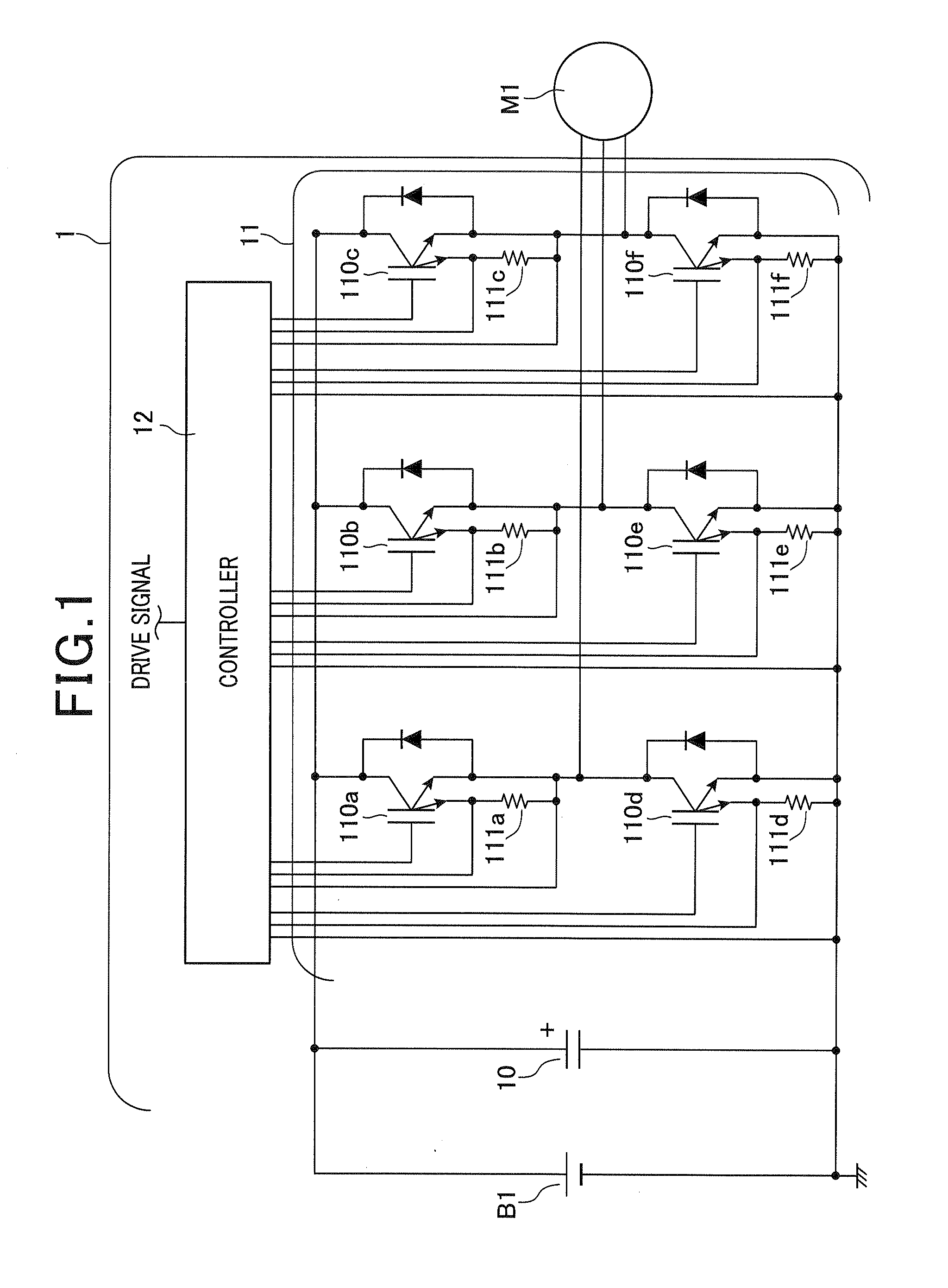
[0023]FIG. 1 shows a circuit diagram of a motor control device as an electronic device in accordance with a first embodiment of the present invention.

[0024]The motor control device 1 converts a DC (direct current) high voltage (e.g., 288V) outputted from a high-voltage battery B1 that is electrically insulated from a vehicle body into a three-phase AC (alternate current) voltage, supplies the three-phase AC voltage to a vehicle drive motor M1, and thereby controls the vehicle drive motor M1. The motor control device 1 includes a smoothing capacitor 10, an inverter 11, and a controller 12.

[0025]The smoothing capacitor 10 is operative to smooth the DC high voltage of the high-voltage battery B1. One end of the smoothing capacitor 10 is electrically connected to a positive electrode terminal of the high-voltage battery B1, and the other end of the smoothing capacitor 10 is electrically connected to a negative electrode terminal of the high-voltage battery B1. The negative electrode ter...

second embodiment

[0063]There will now be explained a motor control device in accordance with a second embodiment of the present invention. In the motor control device of the second embodiment, the current detection circuit and the overcurrent detection circuit share a comparator, while in the motor control device of the first embodiment, the current detection circuit, the overcurrent detection circuit, and the short-circuit detection circuit are separate circuits.

[0064]FIG. 4A shows a circuit diagram of the current detection circuit, the overcurrent detection circuit, and the short-circuit detection circuit in accordance with the second embodiment. Only differences will be described between the first and second embodiments.

[0065]As shown in FIG. 4A, the overcurrent detection circuit 226 includes a comparator 226a, a reference power supply for overcurrent detection 226b, and a reference power supply selector switch 226c. A non-inverting input terminal of the comparator 226a is electrically connected ...

third embodiment

[0076]There will now be explained a motor control device in accordance with a third embodiment of the present invention. In the third embodiment, once an abnormality is detected in the IGBT, the motor control device of the third embodiment clamps the gate voltage of the IGBT at a voltage equal to or lower than the off-state holding threshold for the off-state holding circuit to turn off the IGBT, while the motor control device of the first embodiment cuts off supply of voltage from the drive power supply circuit to turn off the IGBT. The motor control device of the third embodiment is identical to the motor control device of the first embodiment, except for its controller.

[0077]FIG. 5 shows a circuit diagram of the controller in accordance with the third embodiment of the present invention. Only differences will be described herein between the controllers of the first and third embodiments.

[0078]As shown in FIG. 5, the controller 32 includes a drive power supply circuit 320, a turn-...


PUM


Abstract

An electronic device that is capable of detecting an abnormal state such that a switching element is unable to be turned off in spite of a drive signal instructing turn-off of the switching element. The device includes a switching element that is driven by controlling a voltage on its control terminal, a drive circuit that controls the voltage on the control terminal of the switching element on the basis on an inputted drive signal to drive the switching element. In cases where there exists a current flowing through the switching element in spite of the drive signal instructing turn-off of the switching element, the drive circuit determines that the switching element is in an abnormal state, and cuts off supply of voltage from a drive power supply circuit to the control terminal of the switching element to thereby turn off the switching element.

Description

CROSS-REFERENCE TO RELATED APPLICATION[0001]This application is based on and claims the benefit of priority from earlier Japanese Patent Application No. 2010-214148 filed Sep. 24, 2010, the description of which is incorporated herein by reference.BACKGROUND[0002]1. Technical Field[0003]This invention relates to an electronic device that includes a switching element and a drive circuit.[0004]2. Related Art[0005]There is known as an electronic device including a switching element and a drive circuit a power converter as disclosed in Japanese Patent No. 3430878.[0006]The disclosed power converter includes an insulated gate bipolar transistor (IGBT), three metal-oxide-semiconductor field-effect transistors (MOSFETs), and a control circuit. A source terminal, a drain terminal, a gate terminal of a first MOSFET are electrically connected to a power supply for the drive circuit, a gate terminal of the IGBT, and the control circuit, respectively. A source terminal, a drain terminal, and a g...

Claims


Application Information

Patent Timeline
Patent Type & Authority Applications(United States)
IPC IPC(8): H02H3/08H03K3/00
CPCH02M1/32H03K17/0828H02M7/53871
Inventor MIURA, RYOTAROTANIMURA, YASUNARITAKAGI, NORIYUKI
Owner DENSO CORP
Why Eureka
Try Eureka