Ultrasound diagnostic system, ultrasound image generation apparatus, and ultrasound image generation method

an ultrasound image and diagnostic system technology, applied in the field of ultrasound image generation apparatus, ultrasound image generation method, ultrasound diagnostic apparatus, can solve the problems of increasing the size and cost of the apparatus, reducing the ability to draw ultrasound images, and difficulty in separating the doppler signal from the blood vessel and the doppler signal from the puncture needle, etc., to achieve accurate and reliable manner, and easy to be seen by users

Active Publication Date: 2012-03-29
FUJIFILM CORP
View PDF3 Cites 76 Cited by
  • Summary
  • Abstract
  • Description
  • Claims
  • Application Information

AI Technical Summary

Benefits of technology

[0023]The invention has been made in view of the above problems, and a first object of the invention is to solve the problems of the related art and to provide an ultrasound diagnostic apparatus and an ultrasound image generation method capable of displaying the tip end of a puncture tool on an ultrasound image in an accurate, appropriate, and easily visible manner without using a special tool for mechanically vibrating the puncture tool such as a puncture needle and Doppler-mode processing when performing paracentesis.
[0024]A second object of the invention is to provide an ultrasound image generation apparatus and an ultrasound image generation method capable of generating an image for presenting users with the position of a puncture tool such as a puncture needle in an accurate and reliable manner.
[0025]A third object of the invention is to provide an ultrasound image generation apparatus and an ultrasound image generation method capable of generating an ultrasound image in which a puncture tool is displayed to be easily visible to users.
[0026]According to a first aspect of the invention, it is possible to display the tip end of a puncture tool on an ultrasound image in an accurate, appropriate, and easily visible manner without using a special tool for mechanically vibrating the puncture tool such as a puncture needle and Doppler-mode processing when performing paracentesis.
[0027]As a result, according to this aspect, even when a puncture tool such as a narrow puncture needle is used, it is possible to enable the tip end of the puncture tool to reach a target site in a reliable manner.
[0028]According to a second aspect of the invention, it is possible to generate an image for presenting users with the position of a puncture tool such as a puncture needle in an accurate and reliable manner and to specify the accurate position of a puncture tool such as a puncture needle in a reliable manner.

Problems solved by technology

However, in the technique disclosed in Patent Document 1, a special mechanism for mechanically vibrating the puncture needle is needed, which increases the size and cost of an apparatus.
Moreover, when performing ultrasound-guided central venous puncture, there is a problem in that it is difficult to separate the Doppler signal from blood vessels and the Doppler signal from the puncture needle.
However, as the puncture needle becomes narrower, the ability to draw it on an ultrasound image also decreases, and the puncture needle is displayed in a disconnected manner.
Thus, there is a problem in that it is difficult to display the position or shape of the puncture needle precisely.
However, as described above, when a narrow puncture needle is used, the B-mode ultrasound tomographic image frame data itself is data with which it is difficult to display the position or shape of the puncture needle precisely.
Thus, there is a problem in that it is difficult to obtain accurate spatial variation data caused by insertion of the puncture needle from the differential data and to obtain an accurate puncture needle image.

Method used


Image

  • Ultrasound diagnostic system, ultrasound image generation apparatus, and ultrasound image generation method
  • Ultrasound diagnostic system, ultrasound image generation apparatus, and ultrasound image generation method
  • Ultrasound diagnostic system, ultrasound image generation apparatus, and ultrasound image generation method

Examples


first embodiment

[0367]FIG. 27 is a functional block diagram showing a configuration of main parts of an example of an ultrasound image generation apparatus according to the first embodiment of the third aspect of the invention.

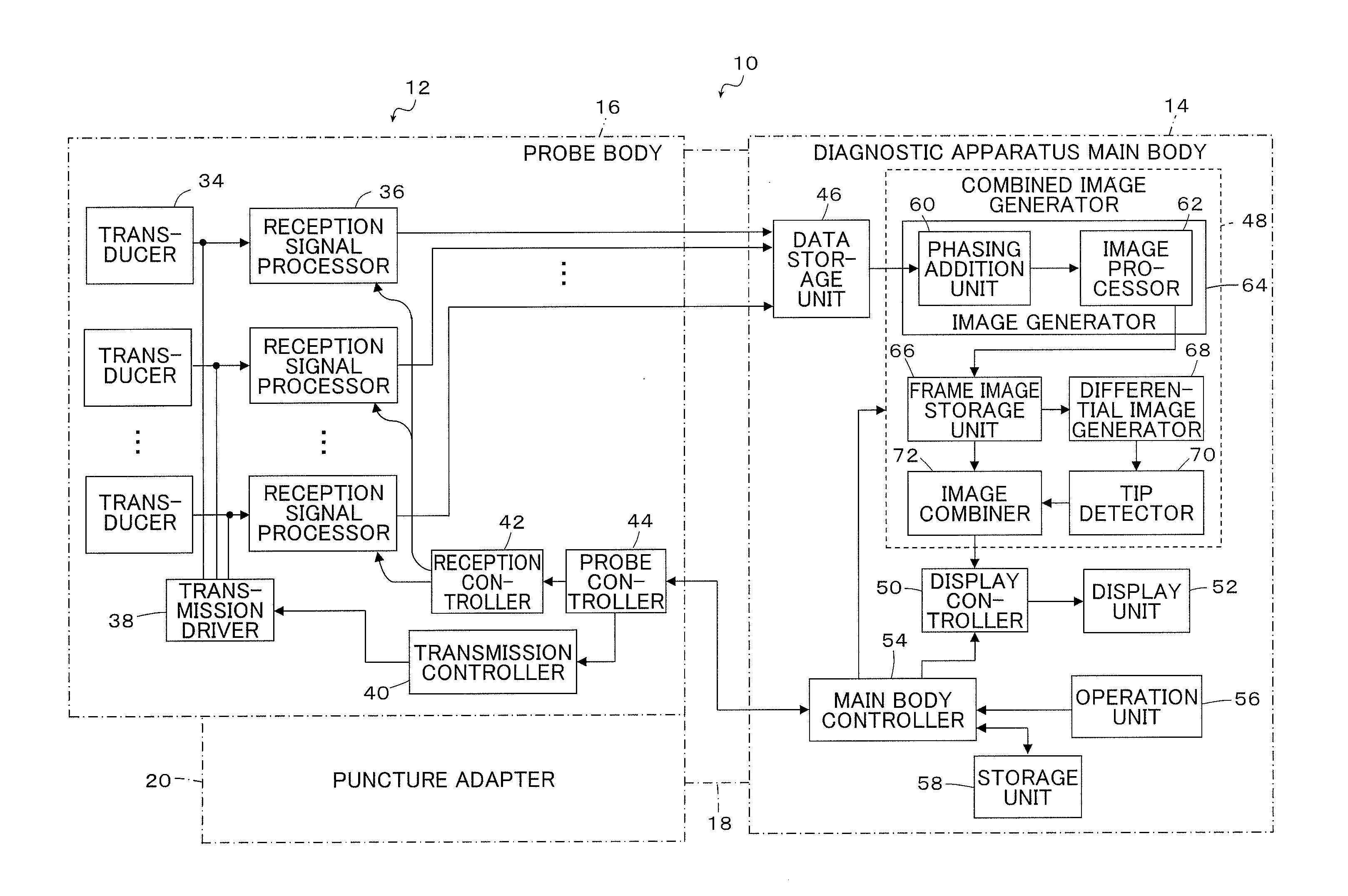
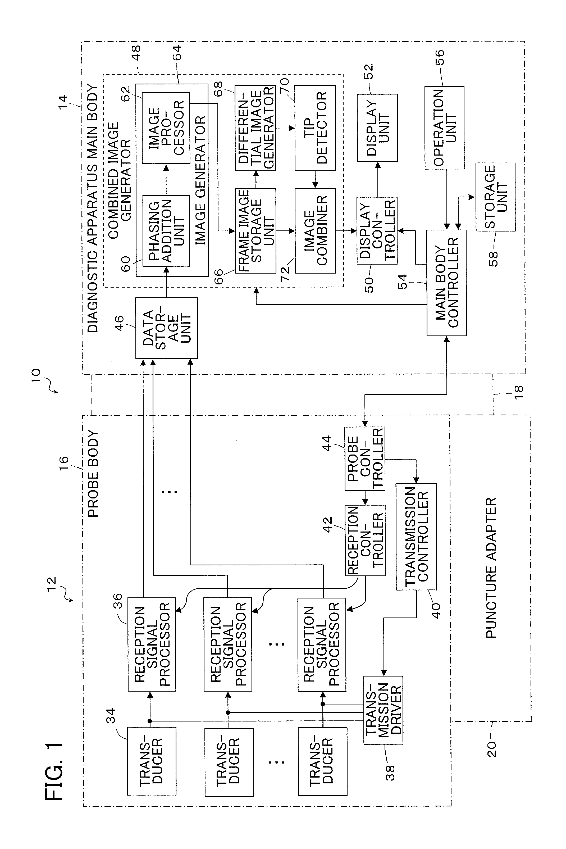
[0368]An ultrasound image generation apparatus 300 shown in FIG. 27 includes a transceiving controller 302, an echo signal storage unit 304, an ultrasound image generator 306, a puncture tool enhancement data generator 308, a puncture tool information storage unit 310, an ultrasound image combiner 312, and an ultrasound image display controller 314. The generation apparatus 300 is used by being electrically connected to a monitor 316 and a probe 318. Moreover, the probe 318 is used together with a puncture adapter 320. The generation apparatus 300, the monitor 316, the probe 318, and the puncture adapter 320 form an ultrasound diagnostic apparatus 10b, and the generation apparatus 300 and the monitor 316 form a diagnostic apparatus main body 14b. Some constituent elements of ...

second embodiment

[0411]In the first embodiment described above, although a case where the pixels located in the insertion direction of the puncture needle are used for weighted addition using a puncture tool enhancement filter having a step shape has been described as an example, the invention is not particularly limited to this. In the second embodiment below, an aspect in which a puncture tool enhancement filter has a rectangular shape, and weighted addition is performed so that the pixels located in the insertion direction of the puncture needle have a large filter coefficient will be described. Since an ultrasound image generation apparatus according to the second embodiment of the present aspect has the same basic configuration as the generation apparatus 300 described in the first embodiment, the functional block diagram thereof will not be illustrated. Moreover, since the basic operation thereof is the same as that of the generation apparatus 300, illustration thereof will not be provided.

[04...

third embodiment

[0425]In the first and second embodiments of the present aspect, the puncture tool enhancement processing was performed on the B-mode image using the puncture tool enhancement filter having a shape corresponding to the insertion angle of the puncture needle. However, in the third embodiment, the B-mode image is rotated in accordance with the insertion angle, and the puncture tool enhancement processing is performed using the same puncture tool enhancement filter.

[0426]FIG. 36 is a block diagram showing a configuration of main parts of an ultrasound image generation apparatus 500 according to the third embodiment of the present aspect. The same constituent elements as the ultrasound image generation apparatus 300 described in the first embodiment will be denoted by the same reference numerals, and description thereof will not be provided.

[0427]The ultrasound image generation apparatus 500 shown in FIG. 36 is different from the ultrasound image generation apparatus 300 shown in FIG. 2...


PUM


Abstract

The ultrasound diagnostic apparatus, ultrasound image generation apparatus and method transmit ultrasound waves to a subject into which a puncture tool is inserted, receive reflected waves reflected from the subject and the puncture tool, and generate echo signals of time-sequential frames based on the received reflected waves, and generate an ultrasound image of the subject based on the generated echo signals. These apparatus and method generate a differential echo signal between time-sequential frames from the echo signals, perform a tip detection process based on the differential echo signal to thereby detect at least one tip candidate including a tip end of the puncture tool, highlight a tip candidate of the puncture tool detected to thereby generate a tip image, and display the tip image of the highlighted puncture tool so as to be superimposed on the generated ultrasound image.

Description

BACKGROUND OF THE INVENTION[0001]The present invention relates to an ultrasound diagnostic apparatus, an ultrasound image generation apparatus, and an ultrasound image generation method. More particularly, the invention relates to an ultrasound diagnostic apparatus, an ultrasound image generation apparatus, and an ultrasound image generation method used when displaying a puncture tool on a screen together with body tissues, specifically when displaying the tip end of a puncture tool such as a puncture needle in an ultrasound image in an accurate and appropriate manner when performing paracentesis.[0002]In medical fields, an ultrasound image generation apparatus for generating ultrasound images and an ultrasound diagnostic apparatus using the generated ultrasound images have been put into practical use and are used widely for diagnosis and examination. In general, this kind of ultrasound image generation apparatus and ultrasound diagnostic apparatus (hereinafter referred collectively...

Claims


Application Information

Patent Timeline
Patent Type & Authority Applications(United States)
IPC IPC(8): A61B8/14
CPCA61B8/0841A61B8/461A61B8/5215A61B10/0233A61B2019/5276G06T7/0042G06T5/50G06T2207/10132G06T2207/20221G06T2207/30021A61B2019/5425A61B2090/378A61B2090/3925G06T7/73G16H50/20A61B8/14A61B8/463A61B8/5207A61B8/5223A61B8/5246A61B8/5269A61B8/54A61B2017/3413A61B2560/0475
Inventor TASHIRO, RIKAKATSUYAMA, KIMITOMIYACHI, YUKIYA
Owner FUJIFILM CORP
Why Eureka
Try Eureka