Boronized laying pipe

a technology of laying pipes and boronized slurry, which is applied in the direction of solid-state diffusion coating, coatings, manufacturing tools, etc., can solve the problems of affecting the useful life of laying pipes, affecting the uniformity of cooling, so as to increase the resistance of laying pipes and increase the useful life of such pipes

Inactive Publication Date: 2012-04-05
PRIMETALS TECH USA
View PDF1 Cites 1 Cited by
  • Summary
  • Abstract
  • Description
  • Claims
  • Application Information

AI Technical Summary

Benefits of technology

[0009]A primary objective of the present invention is to increase the resistance of laying pipes to frictional wear occasioned by contact with hot rolled products, and thereby increase the useful life of such pipes.
[0010]A companion objective of the present invention is to make it possible to reduce the bore size of the laying pipes and thereby improve product guidance and the consistency of ring formation resulting from Such bore size reductions.

Problems solved by technology

At such speeds, the hot rolled products exert a punishing effect on the laying pipes, causing internal pipe surfaces to undergo rapid localized wear and premature failure.
Unstable ring patterns disturb cooling uniformity and also contribute to coiling mishaps, commonly referred to as “cobbling”, at the reforming station.
Frequent and costly mill shutdowns are required to replace prematurely worn laying pipes and to address problems associated With cobbling at the reforming station.
For various reasons, none of these approaches has proven to be a practical solution to the problem of premature pipe wear.
However, the carburizing process requires a drastic quenching from elevated processing temperatures, which can distort the pipe curvature.
Carburized layers have also been found to be relatively brittle and to temper down at elevated temperatures resulting from exposure to the hot rolled products.
Unfortunately, however; these advantages have been offset to a large extent by significantly accelerated pipe wear.
Thus, in the past, those skilled in the art have deemed it necessary to compromise by employing larger bore laying pipes and rolling at reduced speeds below the rated design speeds of the mills.

Method used


Image

  • Boronized laying pipe
  • Boronized laying pipe
  • Boronized laying pipe

Examples


Embodiment Construction

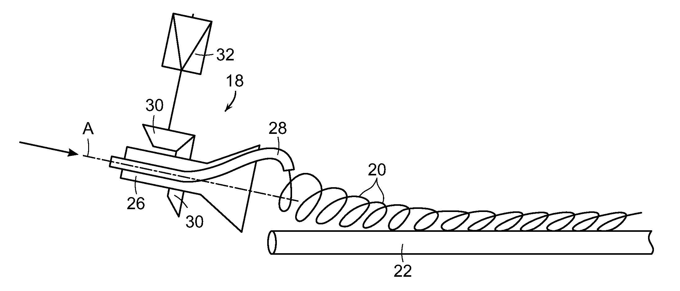
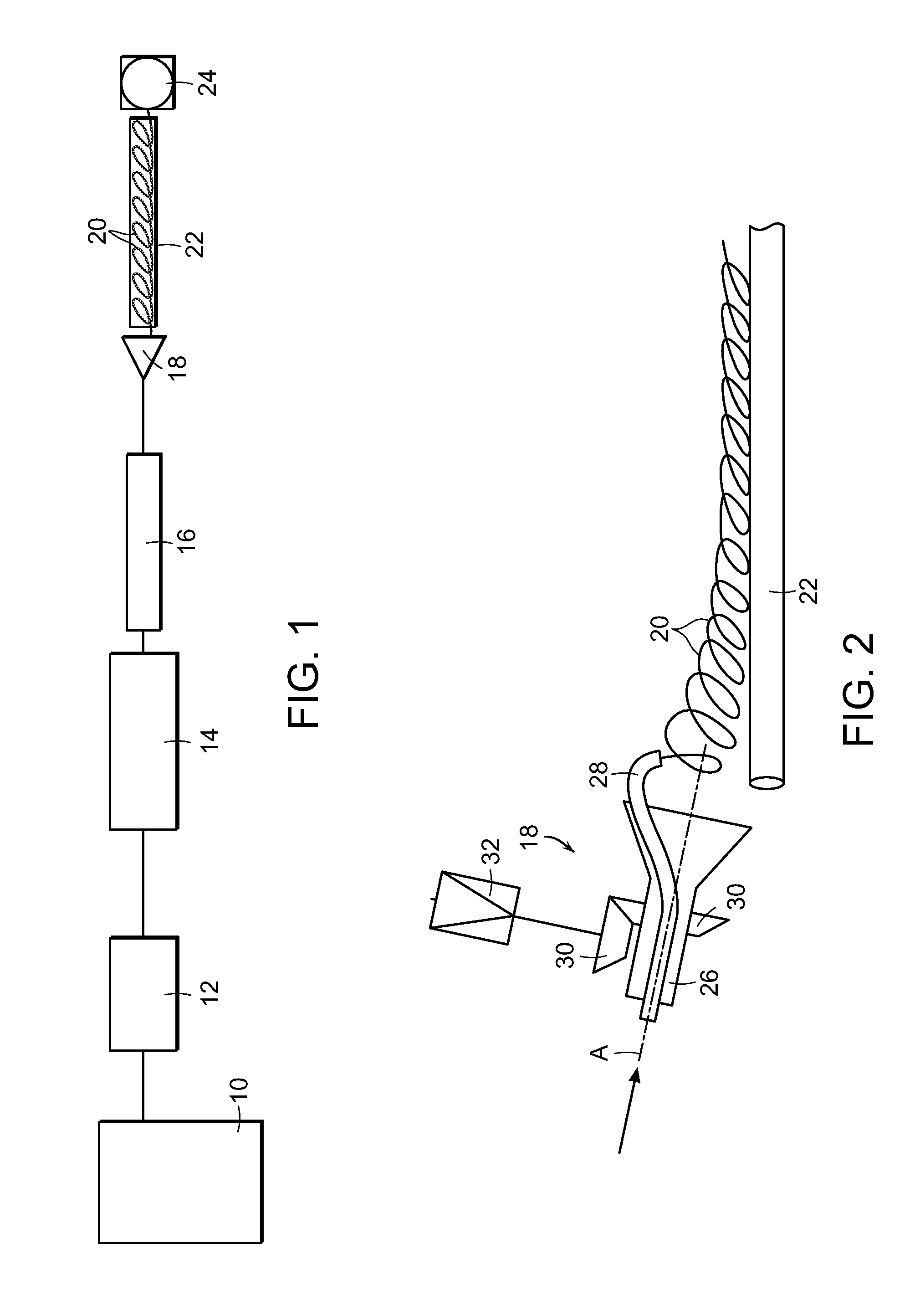
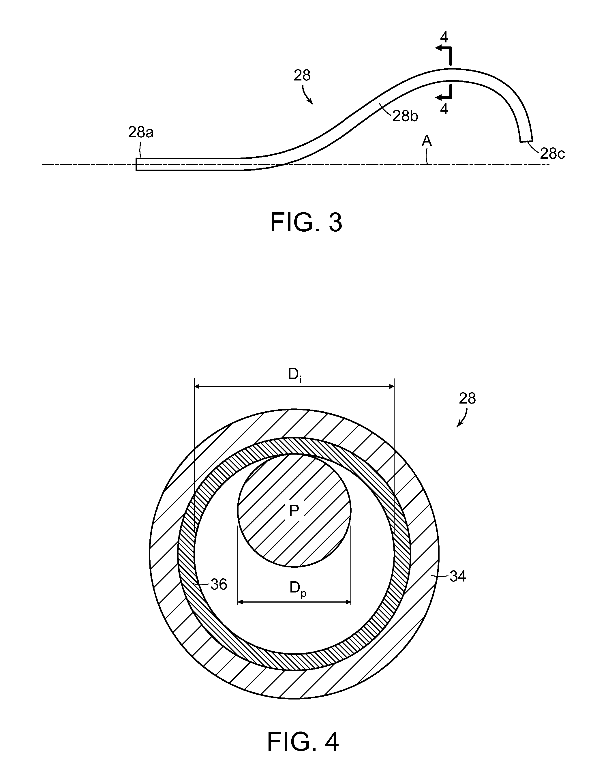
[0016]With reference to FIGS. 3 and 4, a laying pipe 28 in accordance with the present invention is configured for rotation about axis A. The pipe has an entry and 28a aligned on axis A to receive a hot rolled product, with a curved section 28b leading to a delivery end 28c spaced radially from axis A. The curved section defines a guide path configured to form the product into a helical formation of rings (as shown at 20 in FIGS. 1 and 2). As shown in FIG. 4, the laying pipe comprises a ferrous wall 34, with an interior surface layer 36 against which a hot rolled product P is confined for movement along the guide path defined by the pipe. The ferrous wall 34 has a hardness of between about 330-430 knoop (HK100). The interior surface layer 36 comprises a wear resistant boronized layer with an elevated hardness of between about 1600-2300 knoop (HK100).

[0017]The boronized layer 36 results from subjecting the interior pipe surface to a thermochemical treatment in which boron atoms are d...


PUM

PropertyMeasurementUnit
temperatureaaaaaaaaaa
speedsaaaaaaaaaa
temperatureaaaaaaaaaa

Abstract

A laying pipe for use in the laying head of a rolling mill is configured for rotation about an axis, with an entry end aligned on that axis to receive a hot rolled product, and with a curved section leading to a delivery end spaced radially from that axis. The curved section defines a guide path configured to form the hot rolled product into a helical formation of rings. The laying pipe comprises a tubular ferrous wall having an interior surface comprising a wear resistant boronized layer against which the hot rolled product is confined for movement along the guide path.

Description

FIELD OF THE INVENTION[0001]This invention relates generally to the laying pipes employed in rolling mill laying heads to form hot rolled products into helical ring formations, and is concerned in particular with improving the resistance of such pipes to frictional wear caused by contact with the hot rolled products.BACKGROUND DISCUSSION[0002]In a typical rod rolling mill, as depicted diagrammatically in FIG. 1, billets are reheated in a furnace 10. The heated billets are extracted from the furnace and rolled through a roughing mill 12, an intermediate mill 14, and a finishing mill 16 followed in some cases by a reducing / sizing mill (not shown). The finished products are then directed to a laying head 18 where they are formed into rings 20. The rings are deposited on a conveyor 22 for transport to a reforming station 24 where they are gathered into coils. While in transit on the conveyor, the rings are subjected to controlled cooling designed to achieve selected metallurgical proper...

Claims


Application Information

Patent Timeline
Patent Type & Authority Applications(United States)
IPC IPC(8): B21C47/14B23P15/00B23P17/00
CPCB21C47/143C23C8/06C23C8/38C23C8/70Y10T29/49888B21D7/162B23P11/00Y10T29/49986Y10T29/49982B05D7/222
Inventor FIORUCCI, KEITHLASHUA, CHRISTOPHER
Owner PRIMETALS TECH USA
Why Eureka
Try Eureka