
Power cable with a water barrier laminate

a technology of power cables and water barrier laminates, applied in the direction of insulated cables, conductors, climate change adaptation, etc., can solve the problems of increasing the cost of discarding heavy cables, increasing the cost of electric breakdowns, so as to achieve the effect of reducing the total weight of the water barrier concep

Inactive Publication Date: 2012-04-05
NEXANS
View PDF14 Cites 6 Cited by
  • Summary
  • Abstract
  • Description
  • Claims
  • Application Information

AI Technical Summary

Benefits of technology

[0009]The present invention seeks to provide a power cable with a flexible non electrically insulating water barrier layer that can replace a conventional water barrier made from lead. Its most important advantage is its flexibility and significantly a lower weight of the total water barrier concept.

Problems solved by technology

For example, in cable insulation made from for example polymers, or oil impregnated paper, there are possibilities for water treeing when the humidity is above a certain level that after some time may lead to electrical breakdowns.
Particularly with large high voltage underwater cables, the weight issue is important because lead contributes much to the total weight.
Heavy cables add cost in the whole value chain; in production, under transport, storage and deployment.
Even when the cable reaches its economic lifetime, discarding a heavy cable adds cost.
One other problem with lead is when cables are used dynamically, i.e. when the cable is not used in a fixed position.
Lead sheath has a low fatigue limit, making it unsuitable for dynamic applications.
Besides, lead is considered as non-environmentally friendly and for some markets replacement of lead is required.
For long high voltage underwater cables, capacitive charges and resulting currents will initiate problems if not dealt with.
One alternative, not very convenient in subsea cables, is to have controlled discharging of capacitance at regular intervals.
The added cost of using discontinuous deployed cables makes this alternative a prohibitive solution.
However, such corrugated aluminum barriers are normally used on and cables, not on subsea cables.

Method used


Image

  • Power cable with a water barrier laminate
  • Power cable with a water barrier laminate

Examples


Embodiment Construction

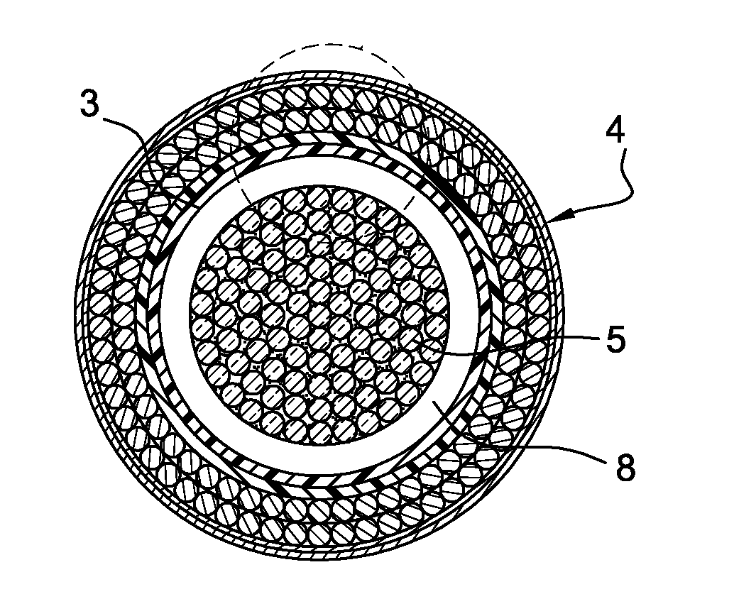
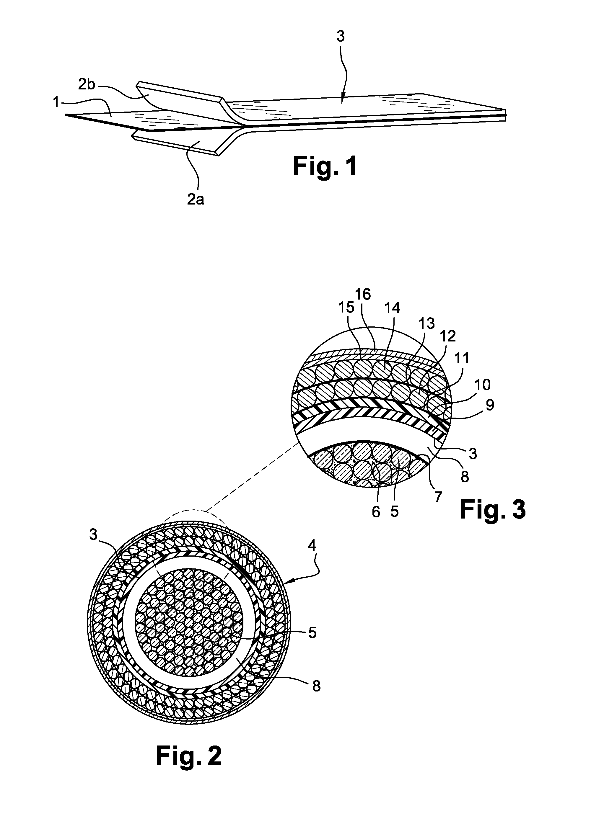
[0019]Referring to FIG. 1, three layers 1, 2a, 2b are shown for this preferred embodiment of a water barrier laminate included in a power cable according to the invention. In the middle is a foil 1 of aluminum or some other similar metal, herein after referred to as metal or aluminum, and on both sides semiconducting polymer layers 2a and 2b are attached. The aluminum is intended to act as a water barrier and an electrical conducting layer and may have any thickness. In a preferred embodiment it may be around 10 micrometers thick.

[0020]The polymer layers 2a, 2b may be made from semiconductive polymer films, such as for instance polyolefin. These films 2a, 2b are made semiconductive for instance by including carbon black containing polyethylene. The thickness of these layers may also vary widely, and in a preferred embodiment each of them may have a thickness of about 50 micrometers.

[0021]The semiconductive layers 2a, 2b contribute to making the laminate 3 more robust and easy to han...


PUM


Abstract

A power cable having a water barrier laminate where the water barrier laminate has foil made of metal (1) laminated between at least two layers of non insulating polymer foils (2a, 2b) constituting a final laminate (3) that is non insulating.

Description

RELATED APPLICATION[0001]This application claims priority to Norwegian Patent Application No. 2010 1359, filed on Sep. 30, 2010, the entirety of which is incorporated by reference.FIELD OF THE INVENTION[0002]The present invention relates to power cables comprising water barriers, and for example to water submerged high voltage cables. Moreover, the present invention also concerns methods to construct such water barriers.BACKGROUND OF THE INVENTION[0003]In subsea cable installations, the cable insulation must be protected from humidity that may lead to electrical breakdown. For example, in cable insulation made from for example polymers, or oil impregnated paper, there are possibilities for water treeing when the humidity is above a certain level that after some time may lead to electrical breakdowns. Different types of water barriers are used in different cable constructions, but the dominating material used for water barriers is lead. This is particularly the case for high voltage ...

Claims


Application Information

Patent Timeline
IPC IPC(8): H01B9/00
CPCH01B7/28Y02A30/14H01B7/14H01B9/00
Inventor FURUHEIM, KNUT MAGNEHVIDSTEN, SVERRE
Owner NEXANS
Learn More