Controller with Valley Switching and Limited Maximum Frequency for Quasi-Resonant Power Converters

a controller and power converter technology, applied in the direction of electric variable regulation, process and machine control, instruments, etc., can solve the problems of increasing switching loss, reducing efficiency under light-load conditions, and quasi-resonant power converters, and achieve the effect of hypersteresis

Active Publication Date: 2012-04-05
SEMICON COMPONENTS IND LLC
View PDF4 Cites 22 Cited by
  • Summary
  • Abstract
  • Description
  • Claims
  • Application Information

AI Technical Summary

Benefits of technology

[0011]The present invention also provides a method for switching a power converter. The method comprises: generating a switching signal coupled to switch a transformer of the power converter; generating a reset signal in response to a feedback signal; generating a valley signal in response to a signal waveform of the transformer during an off-time of the switching signal; and generating a pulse signal in response to the feedback signal and the valley signal, wherein a maximum frequency of the pulse signal is limited, the reset signal is coupled to disable the switching signal, the pulse signal is coupled to enable the switching signal; the feedback signal is correlated to an output load of the power converter. The method further comprises:

Problems solved by technology

However, the drawback of the quasi-resonant power converter is lower efficiency under light-load conditions.
The increased switching frequen

Method used


Image

  • Controller with Valley Switching and Limited Maximum Frequency for Quasi-Resonant Power Converters
  • Controller with Valley Switching and Limited Maximum Frequency for Quasi-Resonant Power Converters
  • Controller with Valley Switching and Limited Maximum Frequency for Quasi-Resonant Power Converters

Examples


Embodiment Construction

[0027]The following description is of the best-contemplated mode of carrying out the invention. This description is made for the purpose of illustrating the general principles of the invention and should not be taken in a limiting sense. The scope of the invention is best determined by reference to the appended claims.

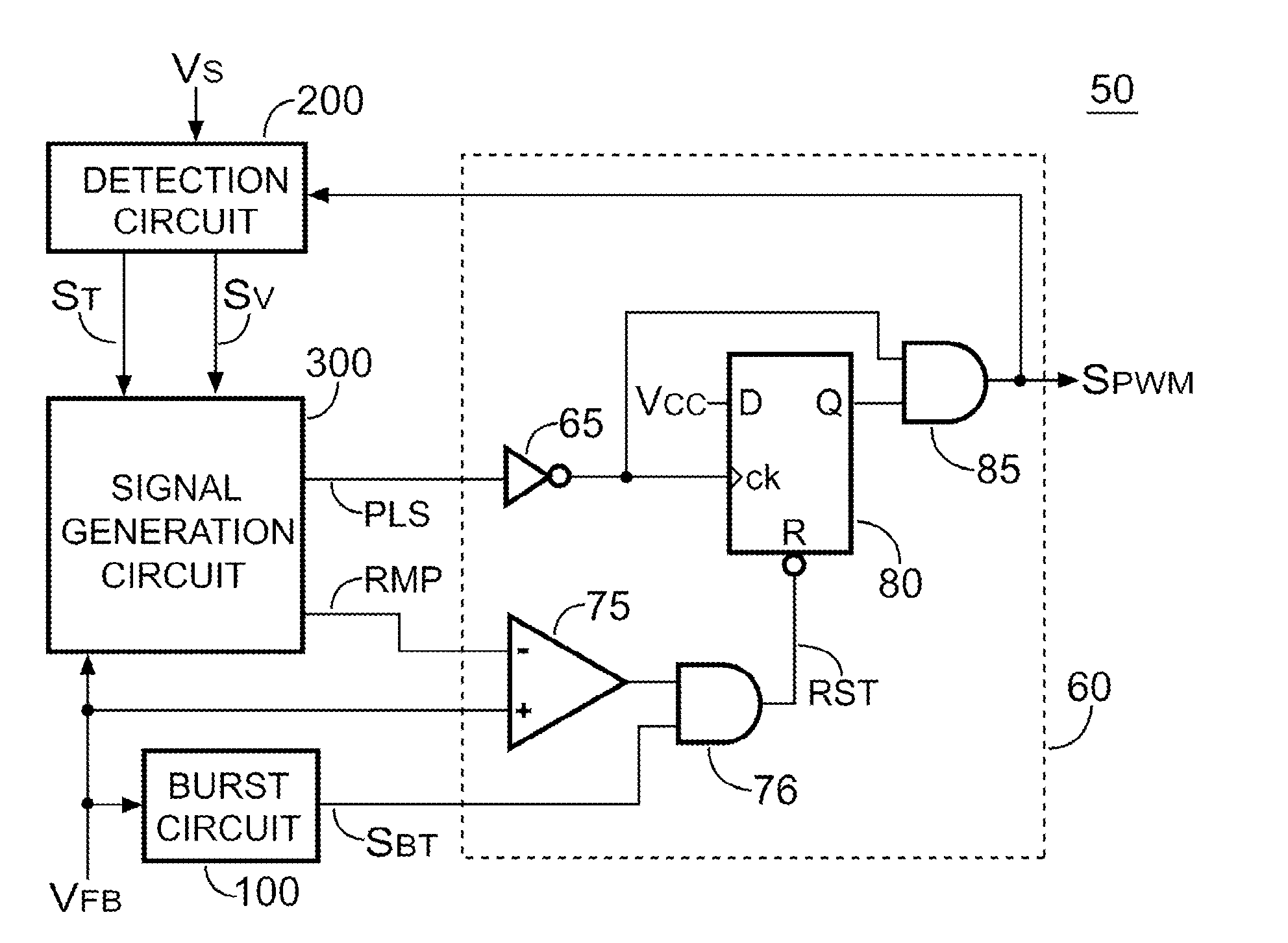
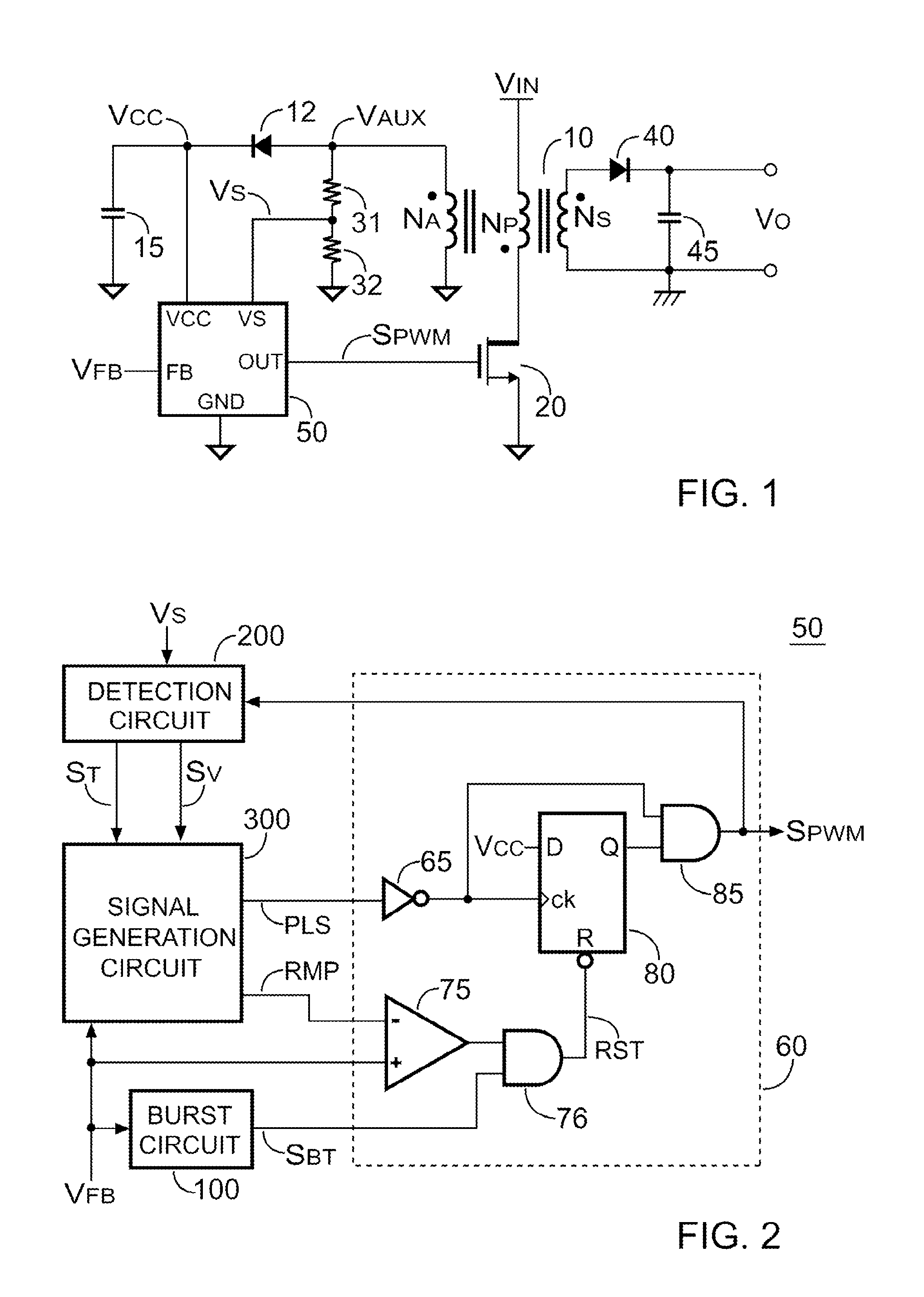
[0028]FIG. 1 shows a quasi-resonant power converter. A transformer 10 has a primary winding NP, an auxiliary winding NA and a secondary winding NS. The primary winding NP is coupled to an input voltage VIN. The secondary winding NS generates an output voltage VO via a rectifier 40 and a capacitor 45. In order to regulate the output voltage VO, a controller 50 generates a switching signal SPWM to switch the transformer 10 via a transistor 20. A feedback signal VFB is correlated to the output voltage VO of the quasi-resonant power converter. In one embodiment of the present invention, the feedback voltage VFB varies in proportion to the output load of the quasi-resonant ...


PUM


Abstract

A controller for a power converter is provided. The controller includes a PWM circuit, a detection circuit, a signal generation circuit and an oscillation circuit. The PWM circuit generates a switching signal coupled to switch a transformer of the power converter. A feedback signal is coupled to the PWM circuit to disable the switching signal. The detection circuit is coupled to the transformer via a resistor for generating a valley signal in response to a signal waveform of the transformer. The signal generation circuit is coupled to receive the feedback signal and the valley signal for generating an enabling signal. The oscillation circuit generates a maximum frequency signal. The maximum frequency signal associates with the enabling signal to generate a pulse signal. The feedback signal is correlated to an output load of the power converter. The maximum frequency of the pulse signal is limited.

Description

CROSS REFERENCE TO RELATED APPLICATIONS[0001]This application claims the benefit of U.S. Provisional Application No. 61 / 388,812, filed on Oct. 1, 2010, the contents of which are incorporated herein by reference.BACKGROUND OF THE INVENTION[0002]1. Field of the Invention[0003]The present invention generally relates to power converters; more specifically, the present invention relates to quasi-resonant power converters.[0004]2. Description of the Related Art[0005]To improve efficiency and reduce power loss at high switching frequency, a quasi-resonant power converter is a solution. The technical details of quasi-resonant power converter can be found in the prior art “Switching Control Circuit Having a Valley Voltage Detector to Achieve Soft Switching for a Resonant Power converter”, U.S. Pat. No. 7,426,120. However, the drawback of the quasi-resonant power converter is lower efficiency under light-load conditions. A switching frequency of the quasi-resonant power converter is varied in...

Claims


Application Information

Patent Timeline
IPC IPC(8): G05F1/575
CPCH02M3/33507Y02B70/16Y02B70/1433H02M2001/0035Y02B70/10H02M1/0035
Inventor YANG, TA-YUNGCHEN, JUNG-SHENGLIN, LI
Owner SEMICON COMPONENTS IND LLC
Why Eureka
Try Eureka