High Voltage High Current Regulator

Active Publication Date: 2012-04-05
ADVANCED FUSION SYST LLC
View PDF1 Cites 25 Cited by
  • Summary
  • Abstract
  • Description
  • Claims
  • Application Information

AI Technical Summary

Benefits of technology

[0020]A high voltage high current vacuum integrated circuit comprises a common vacuum enclosure. The vacuum enclosure contains (1) at least one internal vacuum pumping means; (2) at least one exhaust tubulation for evacuating the vacuum enclosure and subsequently sealing and separating the vacuum enclosure from at least one external vacuum pump; (3) vacuum-sealed electrically-insulated feedthroughs passing electrical conductors from outside the vacuum enclosure to inside the enclosure while electrically insulating the electrical conductors from the vacuum enclosure and maintaining the vacuum seal; and (4) internal ele

Problems solved by technology

With regard to large-scale electrical power grids operating at high voltage and high current, one of the most significant problems is that of limiting fault current.
This creates a cost overhead factor that can be on the order of 75% above what would be needed if the grid was designed only for the actual load capacity.
None of these techniques is capable of meeting the needs of the electric power industry.
Further, prior art technologies are limited in voltage- and current-handling capacity due to the intrinsic nature of their design.
Purely resistive current limiting is the oldest and the least efficient method of limiting current.
Excess current is converted directly to heat, so that efficiency is very low.
A disadvantage of inductive current limiting is that current is shifted out of phase with the voltage, resulting in a poor power factor.
This becomes problematic on high power systems, since the power handling and voltage-withstand ratings of inductors and capacitors are limited.
However, the reliability of superconducting technology is hampered by the need for complex cryogenic refrigeration systems to maintain the superconducting elements at or below their critical temperature.
Aside from an unreliable system design due to complex mecha

Method used


Image

  • High Voltage High Current Regulator
  • High Voltage High Current Regulator
  • High Voltage High Current Regulator

Examples


Embodiment Construction

[0035]A list of reference numerals and associated parts appears near the end of this detailed description.

[0036]The following definitions relate to terms that used herein.

Definitions

[0037]“Electrical power grid” means herein an electrical power and distribution grid for powering private residences, industry and government users. Typically, an electrical power grid will have a plurality of power generators and a means for transmission of electricity to a plurality of distribution substations, the function of which substations is to distribute power to private residences, industry and government users.

[0038]“Fault current” means a severe over-current condition.

[0039]“High current” means herein greater than 50 Amps.

[0040]“High voltage” means herein greater than 400 Volts AC.

High Voltage Current Regulator

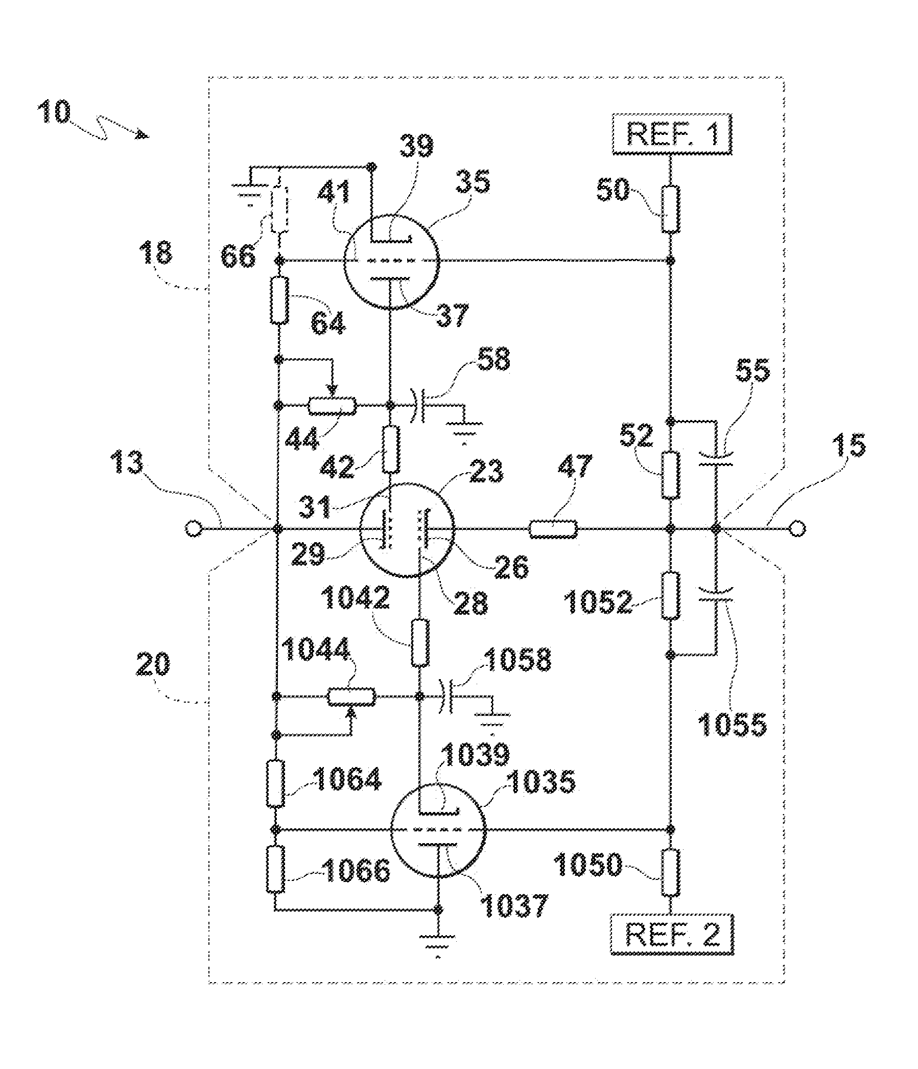
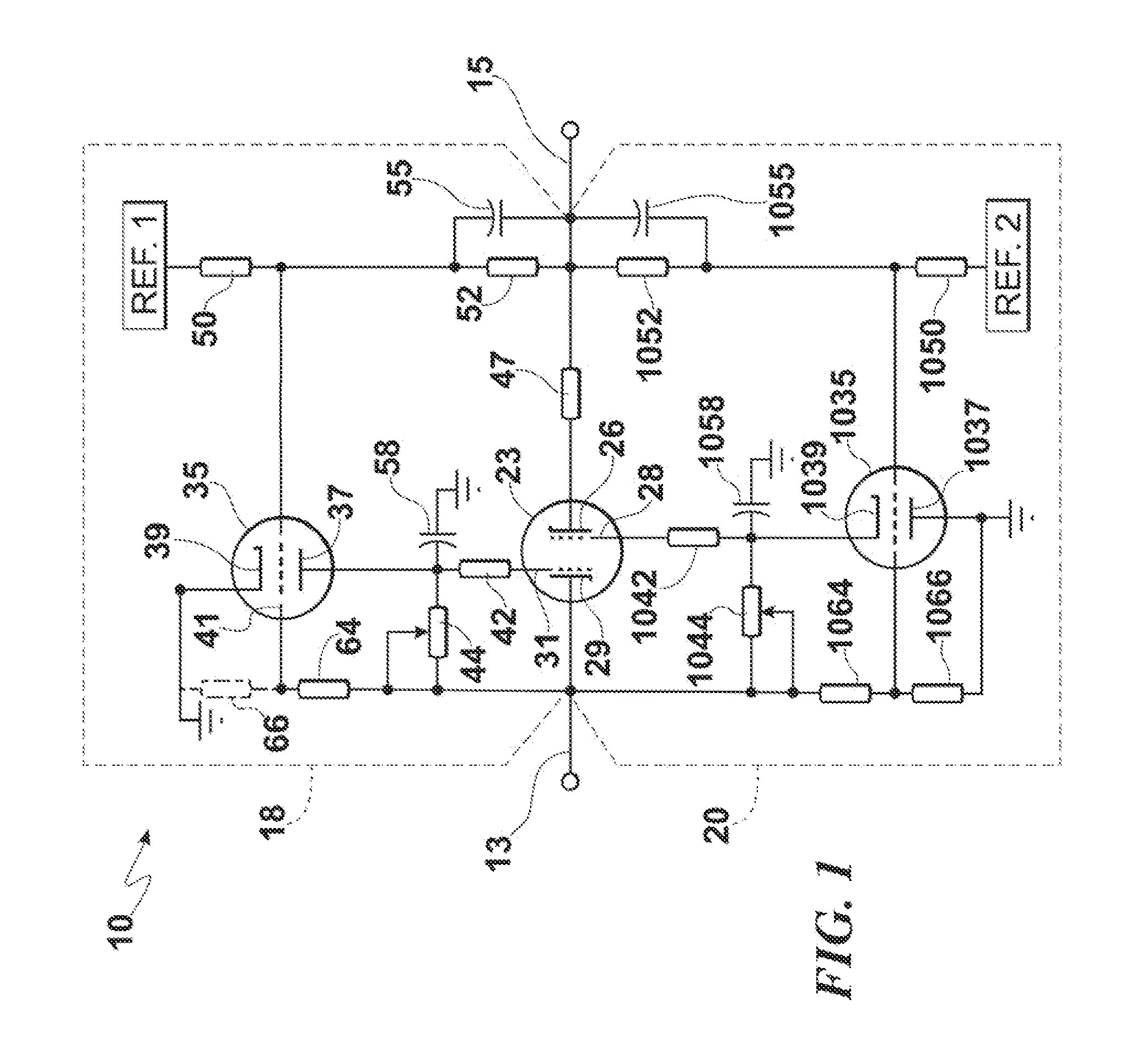
[0041]In accordance with a first aspect of the invention, FIG. 1 shows a high voltage current regulator circuit 10 having first and second terminals 13 and 15 for being interposed in an...


PUM


Abstract

High voltage high current regulator circuit for regulating current is interposed between first and second terminals connected to an external circuit and comprises at least one main-current carrying cold-cathode field emission electron tube conducting current between the first and second terminals. First and second grid-control cold-cathode field emission electron tubes provide control signals for first and second grids of the at least one main-current carrying cold-cathode field emission electron tube for positive and negative excursions of voltage on the first and second terminals, respectively. The current regulator circuit may be accompanied by a voltage-clamping circuit that includes at least one cold-cathode field emission electron tube. At least two cold-cathode field emission electron tubes, configured to operate at high voltage and high current, are preferably contained within a single vacuum enclosure and are interconnected to provide a circuit function, so as to form a high voltage high current vacuum integrated circuit.

Description

CROSS-REFERENCE TO RELATED APPLICATIONS[0001]This application is related to two prior applications by the current inventor, U.S. application Ser. No. 12 / 359,198, filed 23 Jan. 2009, entitled High Voltage Inverter; and U.S. application Ser. No. 12 / 554,818, filed 4 Sep. 2009, entitled Method and Apparatus For Protecting Power Systems From Extraordinary Electromagnetic Pulses.FIELD OF THE INVENTION[0002]The present invention relates to a high voltage, high current regulator circuit, with one aspect relating to controlling high current in a circuit, another aspect relating to clamping a high voltage in a circuit, and yet another aspect relating to a vacuum integrated circuit.BACKGROUND OF THE INVENTION[0003]There is a need for reliable and efficient current regulators, as well as voltage-clamping circuits, for high voltage high power circuits. There are numerous applications for such technology, ranging from critical control functions in the electrical power grid to medical diagnostic a...

Claims


Application Information

Patent Timeline
IPC IPC(8): G05F3/02H01J5/02H01J7/16
CPCG05F1/10H01J21/10H01J19/24H01J19/82H02H9/02H02H3/08H02H9/08H01J19/42H01J19/54H01J19/70G05F1/42H01G4/35H01J5/02H01J7/16
Inventor BIRNBACH, CURTIS A.
Owner ADVANCED FUSION SYST LLC
Why Eureka
Try Eureka