
Multiple Planar Inductor Coaxial Surge Suppressor

a coaxial surge suppressor and multi-planar inductor technology, applied in the direction of overvoltage protection resistors, emergency protective arrangements for limiting excess voltage/current, coupling device connections, etc., can solve the problems of increasing insertion losses, adding manufacturing costs, and increasing manufacturing costs

Active Publication Date: 2007-04-12
COMMSCOPE TECH LLC
View PDF20 Cites 1 Cited by
  • Summary
  • Abstract
  • Description
  • Claims
  • Application Information

AI Technical Summary

Benefits of technology

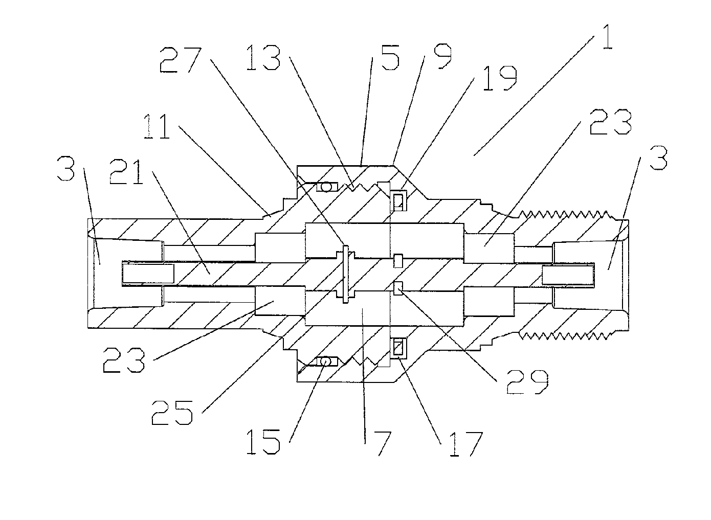
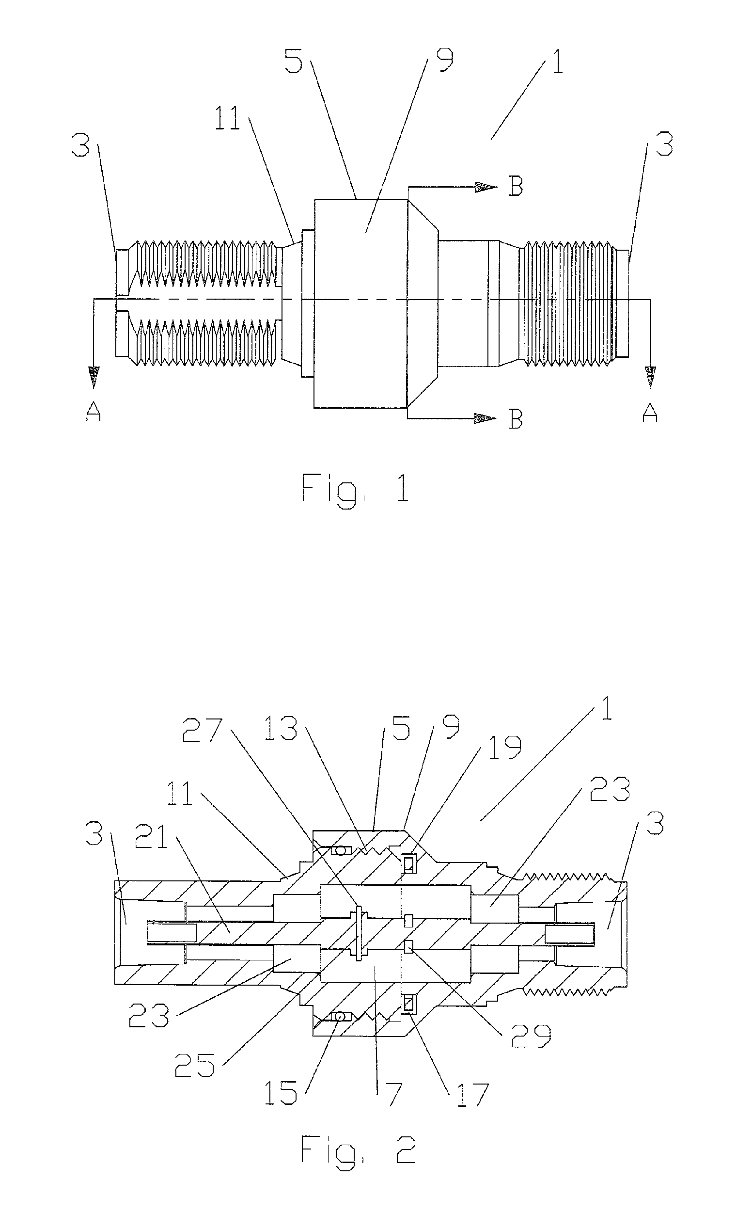
[0015] The inventors have developed an inline surge suppressor with improved current capacity and reduced return loss characteristics. The prior single spiral inductor shorting element is replaced by a shorting element with dual inductor segment pairs coupled to the inner conductor. By extending the shorting element away from the inner conductor along extension segment(s) before initiating curved segment(s) within a channel of the enclosing body (outer conductor), the outer conductor diameter variation and parasitic capacitance between the shorting element and the inner conductor is minimized. Inline surge suppressors according to the invention also have significant manufacturing efficiencies because the shorting element may be stamped and the surge suppressor body components may be configured for manufacture by turning along a single longitudinal axis of the body.
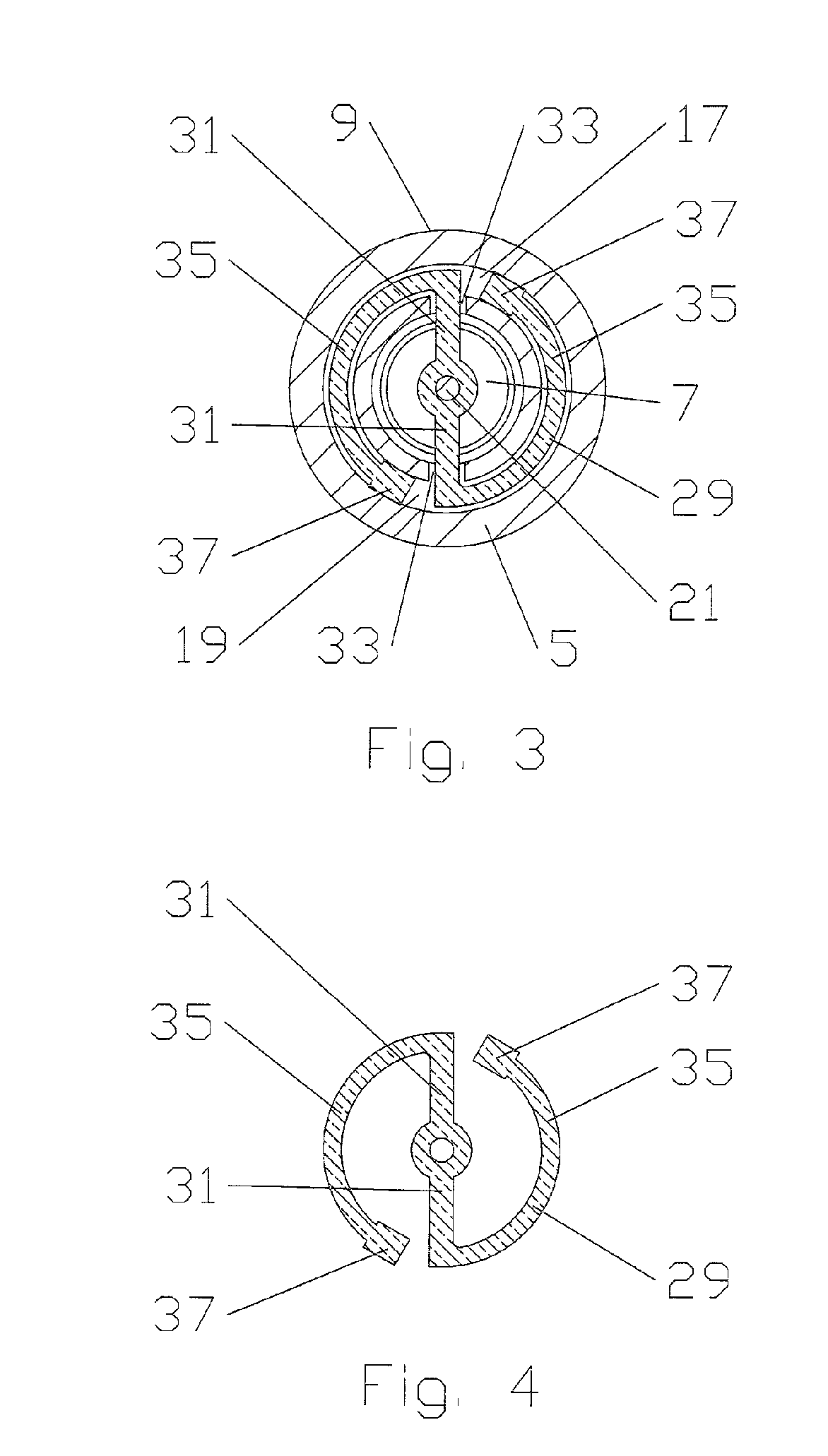
[0019] Upon entering the channel 19, the extension segment(s) 31 become curved segment(s) 35, extending along the channel 19 spaced away or otherwise insulated from the sidewalls of the channel 19. As shown in FIG. 4, a contact 37 dimensioned, for example, with an interference fit within the channel 19 is formed at the distal end of each curved segment 31, coupling the shorting element to the body 5 and thereby to the outer conductor. To reduce the manufacturing precision required, at least the curved segment(s) 35 may be coated with an insulating material, except for the contact(s) 37.
[0021] The length and thereby the associated inductance of each extension and curved segment 31, 35 pair is adjustable by varying the length of the curved segment 35 between a minimum length wherein the extension segment 31 terminates at a contact 37 upon entering the channel 19 and a maximum length with the contact 37 positioned within the channel 19 just short of the next extension segment 31. Where multiple separate but overlapping channel(s) 19 are applied, or a channel wide enough to permit two portions of a curved segment 35 to seat therein without touching one another are applied, the maximum curved segment length may be extended, even further. Within these ranges, the shorting element may be tuned for minimal return losses over a desired frequency band.
[0022] Each of the curved segment(s) 35 are preferably symmetrical with respect to the others, minimizing return losses as each of the inductors formed by the respective extension and curved segment 31, 35 pairs is an equivalent symmetrical inductor in parallel with the others. While the invention has been demonstrated in an exemplary embodiment with dual extension and curved segment 31, 35 pairs it should be understood that, within the scope of the present invention, three, four or more pairs may be applied to the shorting element as desired. Larger numbers of extension and curved segment 31, 35 pairs having the advantage of greater current capacity for a selected segment cross sectional area.
[0023] Because the inductance generated by each extension and curved segment 31, 35 pair is concentrated in the respective curved segment 35, and the curved segment(s) 35 are enclosed within the channel 19, parasitic capacitance present between other curved portions of the shorting element and or the inner conductor of the prior single spiral inductor shorting element surge suppressors is reduced. Also, current carrying capacity is increased through the use of parallel extension and curved segment 31, 35 pairs, minimizing the overall size requirements of the body 5 necessary to contain the shorting element. Further, the isolation of the channel 19 from the inner conductor 21 within the body 5 allows changes to the diameter of the outer conductor along the length of the body 5 to be significantly reduced, thereby reducing the insertion loss of the surge suppressor 1, overall.
[0024] One skilled in the art will appreciate that the present invention also represents a significant improvement in manufacturing efficiency for in-line coaxial surge suppressors. The readily exchangeable surge suppression insert(s) 29 according to the invention have increased segment separation compared to the previous single spiral surge suppression elements permitting precision manufacture of a range of differently dimensioned shorting elements by cost effective stamping processes for a wide range of different frequency bands. Because the majority of body features are annular, turning along a single longitudinal axis may efficiently perform the majority of required body manufacturing operations. Also, surge suppressors according to the invention for specific frequency bands may be quickly assembled for on-demand delivery with minimal lead time, eliminating the need for large stocks of pre-assembled frequency band specific surge suppressor inventory. Further, should a surge suppressor be damaged or the desired frequency band of operation change, the shorting element 29 may be exchanged in the field. Table of Parts1surge suppressor3interface5body7bore9first portion11second portion13thread15gasket17groove19channel21inner conductor23insulator25break27dielectric29shorting element31extension segment33extension groove35curved segment37contact

Problems solved by technology

Where the supporting enclosure and any necessary interface to the surge suppressor body are not machinable along a single longitudinal axis of the surge suppressor body, additional manufacturing costs are incurred.
However, because the shorting element requires sufficient cross sectional area to carry the desired surge current load, the required enclosure is still relatively large and necessarily introduces a significant variation to the outer conductor diameter as it passes along the body of the surge suppressor.
Variations in the outer conductor diameter introduce an impedance discontinuity that increases insertion losses.
Precision manufacture by machining or bending of a range of different spiral inductor shorting element configurations, to allow supply of a surge suppressor optimized for each of a range of different frequency bands, adds a significant manufacturing cost and lead time to the resulting family of surge suppressors.

Method used


Image

  • Multiple Planar Inductor Coaxial Surge Suppressor
  • Multiple Planar Inductor Coaxial Surge Suppressor
  • Multiple Planar Inductor Coaxial Surge Suppressor

Examples


Embodiment Construction

[0015] The inventors have developed an inline surge suppressor with improved current capacity and reduced return loss characteristics. The prior single spiral inductor shorting element is replaced by a shorting element with dual inductor segment pairs coupled to the inner conductor. By extending the shorting element away from the inner conductor along extension segment(s) before initiating curved segment(s) within a channel of the enclosing body (outer conductor), the outer conductor diameter variation and parasitic capacitance between the shorting element and the inner conductor is minimized. Inline surge suppressors according to the invention also have significant manufacturing efficiencies because the shorting element may be stamped and the surge suppressor body components may be configured for manufacture by turning along a single longitudinal axis of the body.

[0016] An exemplary embodiment of the invention is described with reference to FIGS. 1-4. As shown in FIG. 1, a surge s...


PUM


Abstract

An in-line surge suppressor having a body with a bore between two ends and at least one channel located within the body and around the bore. An inner conductor is located within the bore. A shorting element has a plurality of segments that extend from the inner conductor, through extension grooves between the channel and the bore, into a common or separate channel(s). The segments coupled to the channel(s), proximate a distal end of each segment.

Description

BACKGROUND [0001] 1. Field of the Invention [0002] The invention generally relates to surge protection of coaxial cables and transmission lines. More particularly, the invention relates to a compact surge protector with a high current capacity, for use in-line with a coaxial cable or transmission line, configurable for a range of different frequency bands. [0003] 2. Description of Related Art [0004] Electrical cables, for example coaxial transmission lines of antenna towers, are equipped with surge suppression equipment to provide an electrical path to ground for diversion of electrical current surges resulting from, for example, static discharge and or lightning strikes. [0005] Prior coaxial suppression equipment typically incorporated a frequency selective shorting element between the inner and outer conductors dimensioned to be approximately one quarter of the frequency band center frequency in length, known as a quarter wavelength stub. Therefore, frequencies within the operatin...

Claims


Application Information

Patent Timeline
Patent Type & Authority Applications(United States)
IPC IPC(8): H02H9/06H01R24/38
CPCH01R24/48H01R2103/00
Inventor HARWATH, FRANKABURKE, RODGER
Owner COMMSCOPE TECH LLC
Learn More