High speed transformer

Active Publication Date: 2012-04-05
ROCKWELL AUTOMATION TECH
View PDF15 Cites 37 Cited by
  • Summary
  • Abstract
  • Description
  • Claims
  • Application Information

AI Technical Summary

Benefits of technology

[0003]Embodiments of the present disclosure provide novel techniques for using a high speed transformer, such as a pulse transformer, to provide for high speed switching, electrical isolation, and/or generation of a gate signal pulses. The high speed transformer embodiments described herein are simple to manufacture, are more reliable to use, are manufactured of less expensive components, and are capable of high speed switching of signals. In particular, certain embodimen

Problems solved by technology

However, pulse transformers may not

Method used


Image

  • High speed transformer
  • High speed transformer
  • High speed transformer

Examples


Embodiment Construction

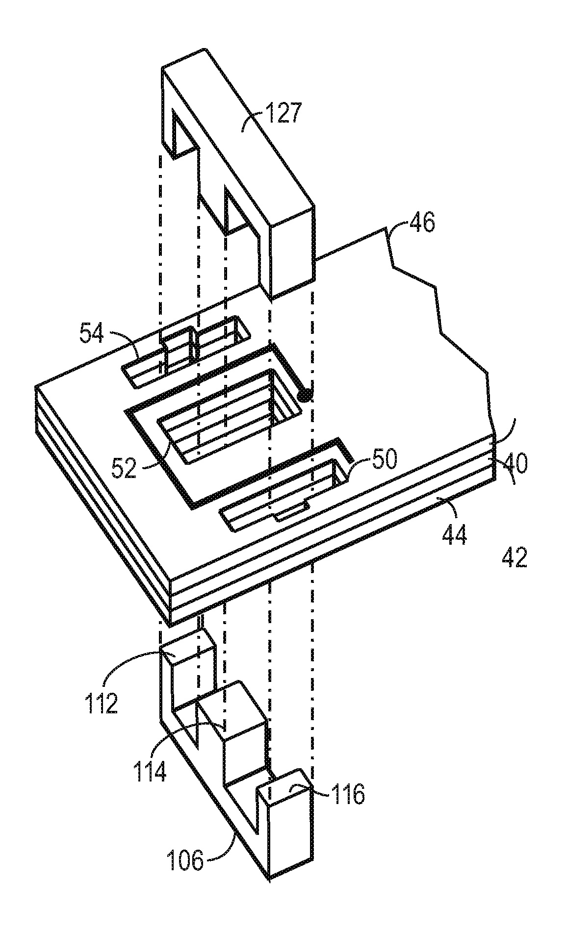
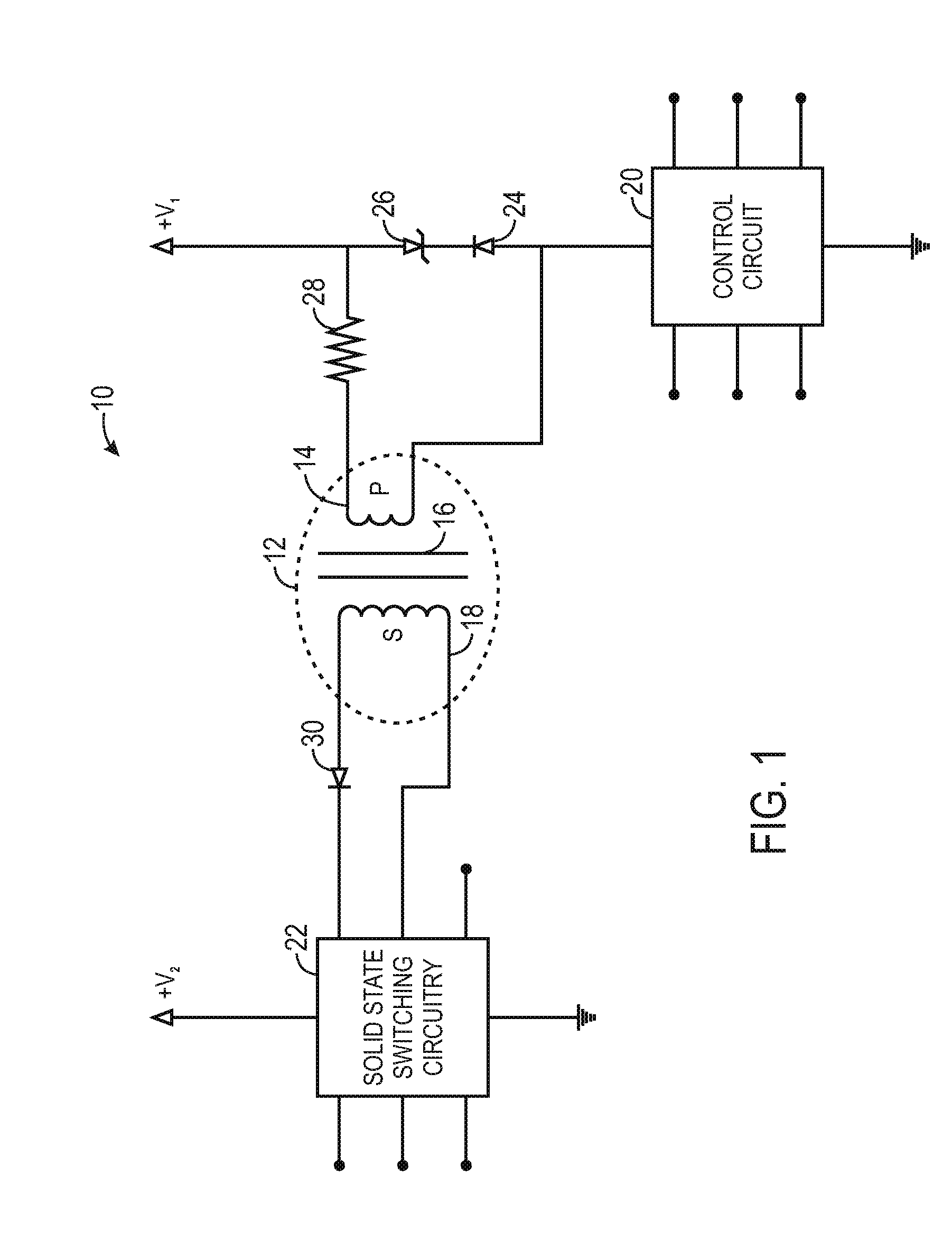
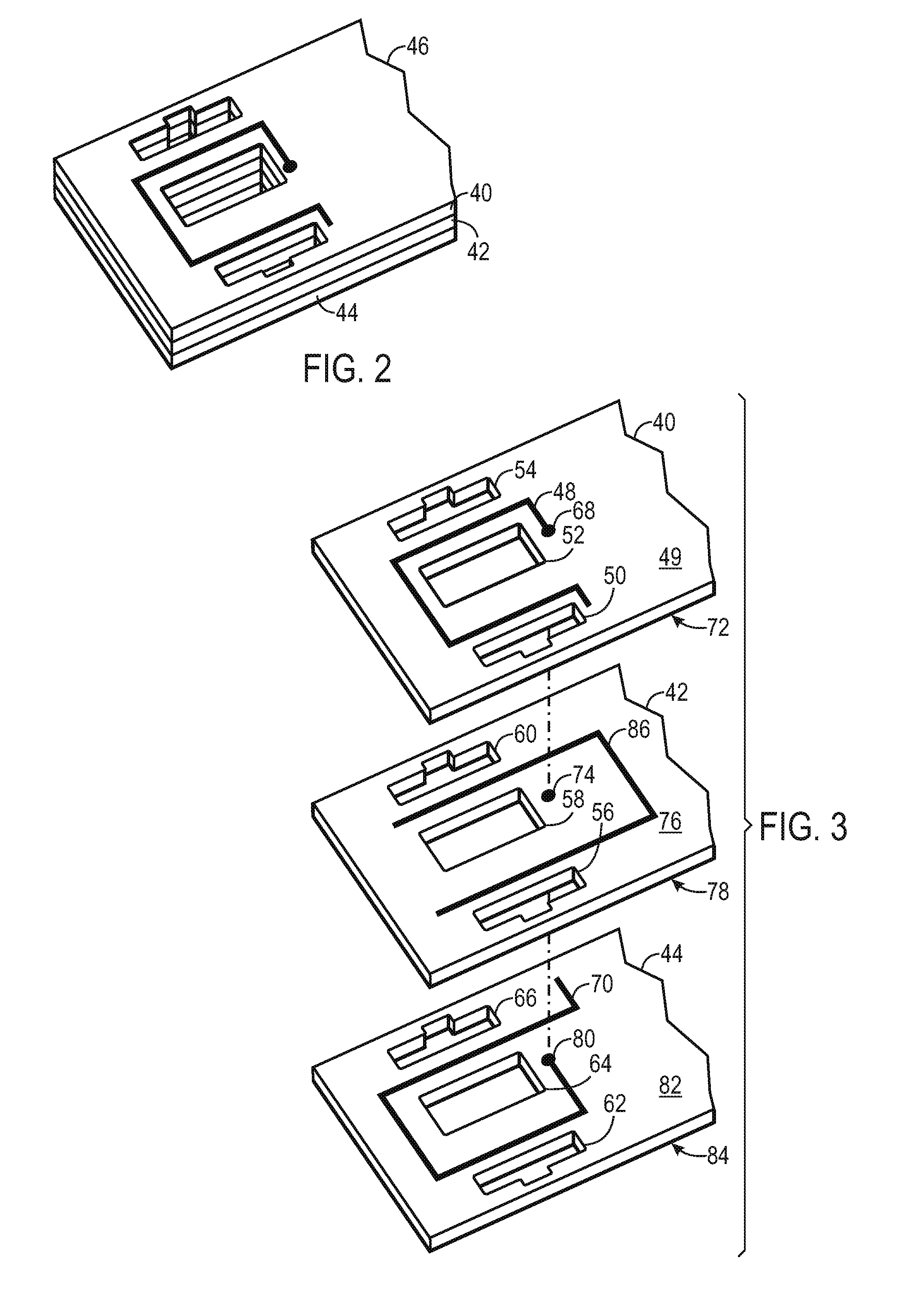
[0019]It may be beneficial to first discuss embodiments of certain transformer systems that may incorporate the techniques described herein. With this in mind and turning now to FIG. 1, the figure is a schematic diagram of an embodiment of an electric circuit 10 including a transformer 12. The electrical circuit 10 of FIG. 1 may be incorporated into electric motor control embodiments, power converter embodiments, photographic flash embodiments, light dimmer embodiments, and so forth. Indeed, the circuit 10 may be used in any number of electrical examples. In certain embodiments, the transformer 12 may be a pulse transformer 12 suitable for high duty cycles (e.g., in excess of 50%) and frequencies in excess of 2 MHz. The transformer 12 includes a primary coil 14, a core 16, and a secondary coil 18. A primary side circuit (e.g., control circuit) 20 enables flow of current into the primary coil 14 of the transformer, which in turn produces a magnetic field. The core 16 may increase the...


PUM


Abstract

Embodiments of the present invention provide novel techniques for creating a high speed transformer such as a pulse transformer. In particular, a secondary coil of the high speed transformer may include a single turn. The use of a single turn secondary coil simplifies the design and manufacture of the transformer and aids in more efficient inspections. Further, the single turn secondary coil transformer may reduce the number of vias used to interconnect the components of the transformer. Additionally, the embodiments described herein may significantly improve voltage isolation by single turn coils, and eliminate vias between board layers.

Description

BACKGROUND[0001]The present invention relates generally to the field of electrical transformers such as those used to control the transfer electrical energy from one circuit to another as well as provide voltage isolation between the control and power circuits. More particularly, the present invention relates to transformers that may be made on or in control electrical circuit boards, and to methods for making such transformers.[0002]High speed transformers are used in a wide range of applications. For example, in power converters capable of converting electrical energy for use with centrifuges, magnetic clutches, pumps and more generally, in electric motor drive controllers that transform and condition incoming AC power for supply to motor drive circuitry. In certain motor drive circuits, silicon controlled rectifiers (SCRs) or other solid state switches are utilized to redirect and rectify incoming AC power and to deliver variable voltage and frequency three-phase power to control...

Claims


Application Information

Patent Timeline
IPC IPC(8): H01F5/00
CPCH01F2027/2809H01F19/04
Inventor NANAYAKKARA, RAVIANNIS, JEFFREY R.BADER, DOUGLAS J.LANGER, RANDALL S.
Owner ROCKWELL AUTOMATION TECH
Why Eureka
Try Eureka