Aircraft icing detector

a technology for detecting aircraft and ice, which is applied in the direction of material analysis, instruments, transportation and packaging, etc., can solve the problems of no simple, cost-effective system, and no system to provide feedback to the pilo

Inactive Publication Date: 2012-04-12
LUMEN INT
View PDF3 Cites 45 Cited by
  • Summary
  • Abstract
  • Description
  • Claims
  • Application Information

AI Technical Summary

Benefits of technology

[0021]FIG. 2 is an illustration showing the moisture effect on ice accretion of two different ice shapes, according to the known art;

Problems solved by technology

It is difficult to see ice or frost (usually clear or whitish) against a light-colored airplane wing from the cockpit, and even if ice is detected visually in flight, it is almost impossible to accurately determine the thickness of the ice and the rate of accumulation.
The basic problem is that there is no simple, cost-effective system that will warn a pilot when he first encounters icing in flight and once in icing conditions, there is no system to provide feedback to the pilot on the effectiveness of his anti-icing procedures.
Current systems do not provide the depth and shape of the ice accretion on the aircraft.
This is important because ice shape and depth greatly affects aircraft performance and stall speed.
For example, ice horns can provide extreme disruption to the airflow over a wing and are often the final icing shape that leads to a stall.
They are created when outward pressure carves ice into two “horns” that disrupt the airflow and decrease the effectiveness of the wing, greatly increasing stall speed.
Currently, icing is difficult or impossible to detect at night.
Large commercial aircraft have wing illumination lights, but the wings are commonly too far behind the cockpit for easy viewing, or the visible portion of the wing is so far away from the cockpit that subtle changes in ice formations are not observable.
Visual inspection is unreliable under conditions of limited visibility brought on by fog, falling snow, freezing rain, and / or by darkness.

Method used


Image

  • Aircraft icing detector
  • Aircraft icing detector
  • Aircraft icing detector

Examples


Embodiment Construction

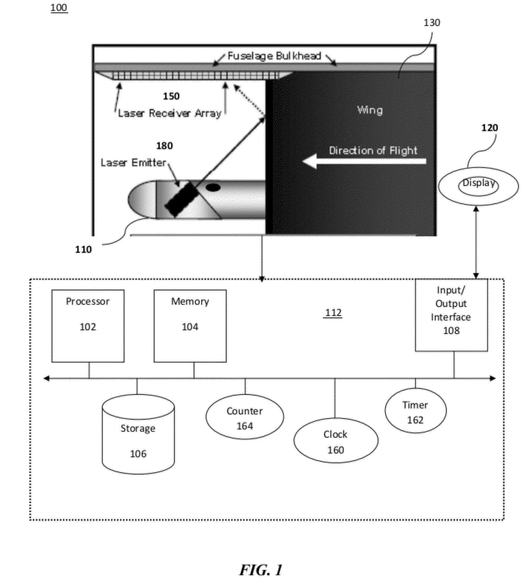
[0049]We describe a system, apparatus, and method for providing a laser-enabled “airframe contamination” alert to provide information on the amount and shape of an accumulation of surface contaminants such as ice or frost, on an airfoil as well as details of the surface contamination event. The system, apparatus, and method are suitable for use in general aviation (private), military, corporate, and commercial aircraft. Embodiments of the invention can also be advantageously employed with unmanned aerial vehicles (UAV).

[0050]An embodiment of the system combines a laser-based surface contaminant detection device with a pilot display to warn pilots of the initial formation of airframe contaminants. The notification and details of the surface contamination event can also be down-linked to the Federal Aviation Administration (FAA) or other agencies via various existing radio frequency (RF) links.

[0051]In the following description, numerous specific details are set forth by way of exempl...


PUM


Abstract

A method for aircraft surface contamination detection and measurement includes: mounting a laser probe on an airfoil; positioning the laser probe to emit laser energy at multiple pre-determined surface points along the leading edge of the airfoil; and using a processor device for activating the laser probe and obtaining measurement data for generating a surface contour of the shape and accurate measurement of the depth of airfoil icing in the surface target area. The icing data is presented to the pilot in a display that alerts him to the icing and accurately shows the depth and shape of the airfoil icing.

Description

CROSS-REFERENCE TO RELATED APPLICATIONS[0001]None.STATEMENT REGARDING FEDERALLY SPONSORED-RESEARCH OR DEVELOPMENT[0002]None.INCORPORATION BY REFERENCE OF MATERIAL SUBMITTED ON A COMPACT DISC[0003]None.FIELD OF THE INVENTION[0004]The invention disclosed broadly relates to the field of ice detection systems for airplanes and more particularly relates to the field of laser-enabled ice detection systems.BACKGROUND OF THE INVENTION[0005]Recent air travel incidents involving ice on aircraft wings have underscored the necessity of detecting the presence, depth, and shape of ice on aircraft wings while in flight. It is difficult to see ice or frost (usually clear or whitish) against a light-colored airplane wing from the cockpit, and even if ice is detected visually in flight, it is almost impossible to accurately determine the thickness of the ice and the rate of accumulation.[0006]The main parts of an airplane are the: cockpit, fuselage, wings, powerplant (engines), landing gear, and the ...

Claims


Application Information

Patent Timeline
Patent Type & Authority Applications(United States)
IPC IPC(8): B64D15/20
CPCB64D15/20G01N21/55G01B11/24
Inventor BARNES, WILLIAM J.
Owner LUMEN INT
Why Eureka
Try Eureka