Blow molding apparatus

a blow molding machine and blow molding technology, which is applied in the field of multi-station blow molding machines or apparatuses, can solve the problems of complicated machine manufacturing, high construction and operation costs of machines, and high cost of changing to a different style of container, so as to reduce the downtime of repair and maintenance increase the productivity of blow molding apparatus, and reduce the effect of downtim

Active Publication Date: 2012-04-12
GRAHAM ENG CO LLC
View PDF5 Cites 8 Cited by
  • Summary
  • Abstract
  • Description
  • Claims
  • Application Information

AI Technical Summary

Benefits of technology

[0013]Another aspect of the invention is directed to a wheel for use in rotary molding machine. The wheel has a first turntable and a second turntable mounted for rotation about a rotational axis. The second turntable is parallel to the first turntable. The first and second turntables extend transversely to the rotational axis. A plurality of modular mold clamp assemblies are provided on the turntable. Each modular mold clamp assembly is moveable between an open and a closed position, and has mounting areas which are mounted with respective mounting locations of each turntable. The modular mold clamp assemblies provide the structure and rigidity between the turntables to help maintain the turntables in position relative to each other.
[0014]Another aspect of the invention is directed to a method of molding parts in the blow molding apparatus which allows for productivity to be increased. The modular mold clamp assemblies are inserted into the movable member. The movable member is rotated about a rotational axis of the base. The components of the movable member are supported through the modular clamp assemblies. Mold halves, which are supported by the modular mold clamp assemblies, are clamped around extruded material. The material is cured in the mold halves and the parts are ejected from the mold halves. This allows the productivity of the molding apparatus to be increased, as the repair and maintenance downtime of the blow molding apparatus is minimized.

Problems solved by technology

These machines are expensive to construct and operate.
Change-over to a different style container is expensive and time-consuming due to the need to build and install a set of new molds on the supports.
Because of the supports and shafts required to properly operate the machines, the machines are complicated to manufacture and require significant expertise and time to repair or replace the mold clamp assemblies.

Method used


Image

  • Blow molding apparatus
  • Blow molding apparatus
  • Blow molding apparatus

Examples


Embodiment Construction

[0033]The rotary blow molding machine described herein is adapted to engage a tubular parison and transform the same into hollow, molded objects, such as containers of various types. As is known in the industry, the parison comprises resin which is homogeniously melted within an extruder of suitable type.

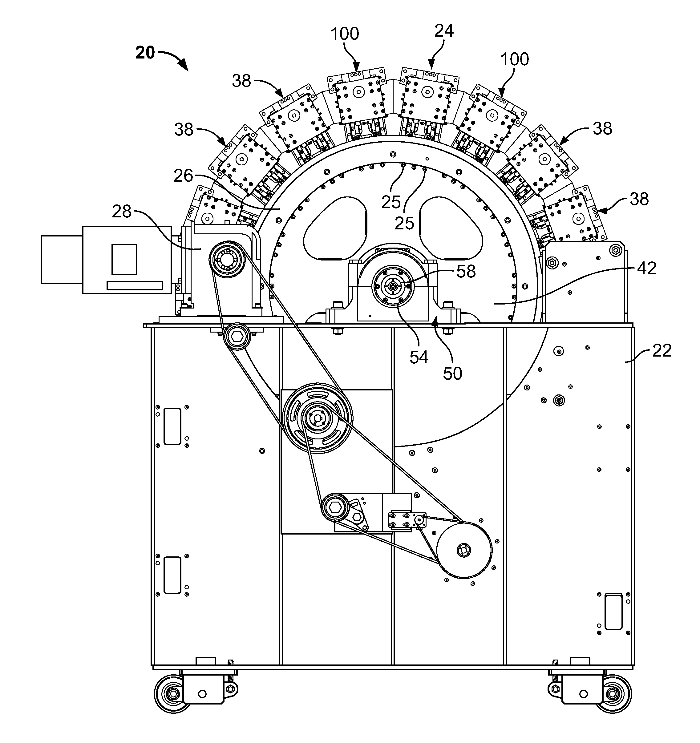
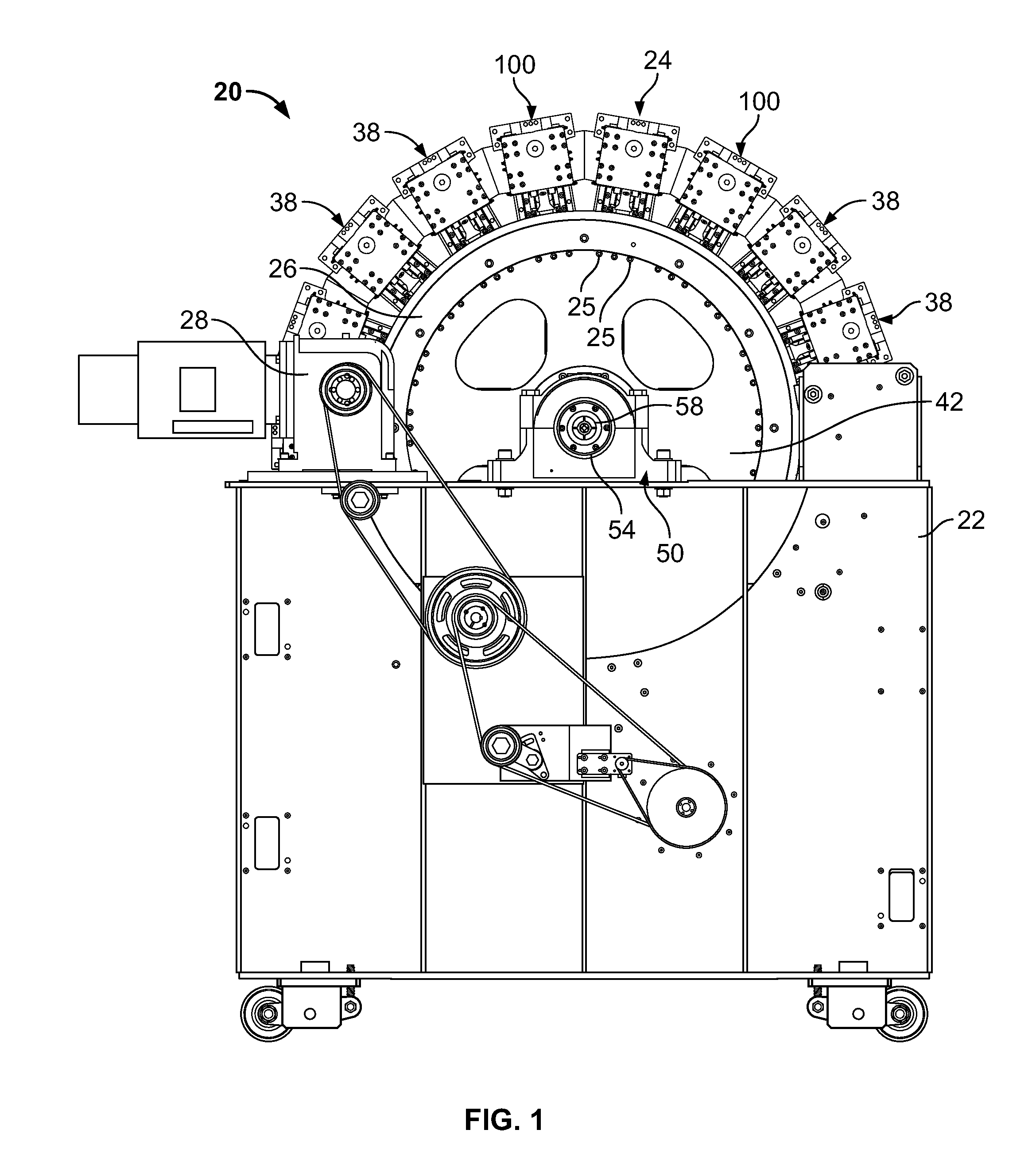
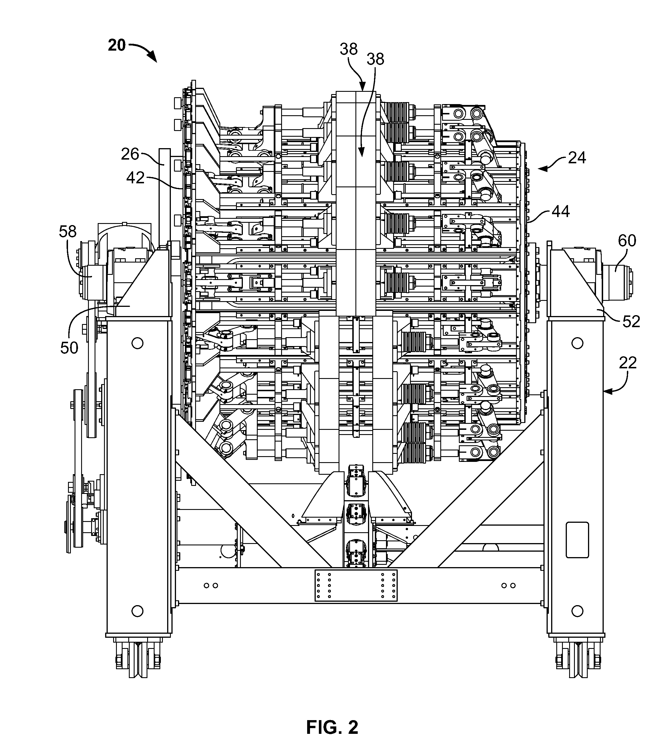
[0034]Referring now to FIG. 1 and FIG. 2, there is illustrated a plastic blow molding machine shown generally by reference numeral 20. The blow molding machine 20 includes a base 22 and a movable member or wheel 24 mounted on the base for rotation thereon about a rotational axis A. The movable member 24 may be in the form of a wheel or other such configurations which are rotatable about the rotational axis. As illustrated, the blow molding machine includes a ring gear or drive gear 26 driven by a drive mechanism 28. The ring gear 26 is mounted to turntable 42 and rotates the wheel 24.

[0035]As best shown in FIG. 1, the plastic blow molding machine 20 includes a plurality of blow mold...


PUM

PropertyMeasurementUnit
rigidityaaaaaaaaaa
axial movementaaaaaaaaaa
diameteraaaaaaaaaa

Abstract

The invention is directed a rotary molding machine having a wheel mounted for rotation on a pair of shafts positioned along the rotational axis of the wheel. A first shaft cooperates with a first turntable of the wheel and a second shaft cooperates with a second turntable. The first and second turntables extend transversely to the rotational axis. A plurality of modular mold clamp assemblies are positioned on the wheel, with each modular mold clamp assembly being moveable between an open and a closed position. Each modular mold clamp assembly has mounting areas which are mounted with respective mounting locations each turntable. The modular mold clamp assemblies provide the structure and rigidity between the turntables to help maintain the turntables in position relative to each other.

Description

FIELD OF THE INVENTION[0001]The present invention is related to a multi-station blow molding machine or apparatus. In particular, the invention relates to a blow molding machine or apparatus in which the components are modular.BACKGROUND OF THE INVENTION[0002]Rotary plastic blow molding machines conventionally include a structural frame or wheel mounted on a base for rotation about a horizontal rotational axis. The wheel includes a frame that supports a plurality of mold stations, each of which are mounted around the circumference of the machine, and each of which has a pair of mold supports for mounting a pair of mold portions of a mold. A continuously extruded parison is guided between open mold halves. With rotation, the molds close on the parison, the parison is blown, the molds open to eject containers, and the cycle is repeated. The molds are continuously rotated at high speed to produce containers in high volumes. These machines are expensive to construct and operate. As many...

Claims


Application Information

Patent Timeline
Patent Type & Authority Applications(United States)
IPC IPC(8): B29C49/36B29C49/48B29C49/00
CPCB29C49/04B29C49/42B29C49/56B29C49/36B29C49/5602B29C49/5603B29C49/561B29C33/22B29C33/36
Inventor MATHY, JR., JOHN M.FIORANI, DAVID N.
Owner GRAHAM ENG CO LLC
Why Eureka
Try Eureka