Wireless communication node connections

a wireless communication node and wireless communication technology, applied in the direction of receiving monitoring, transmission monitoring, line-fault/interference reduction, etc., can solve the problems of difficult and time-consuming physical verification of cabling, often incorrect connection of cables, and difficulty in determining if a connection has been established correctly. , to achieve the effect of fast and reliable determination of connection state, simple and substantially automatic way, and reliable wireless communication nod

Active Publication Date: 2012-04-12
TELEFON AB LM ERICSSON (PUBL)
View PDF35 Cites 18 Cited by
  • Summary
  • Abstract
  • Description
  • Claims
  • Application Information

AI Technical Summary

Benefits of technology

[0010]It is an advantage of the invention that a simple and substantially automatic way of identifying which feeder ports have been connected to which antenna ports is provided. It is particularly an advantage of the invention that a reliable wireless communication node and a method are provided for determining in which order feeder ports have been connected to antenna ports. Particularly it can be carried out without requiring any marking of the cables or substantially without any manual interaction at all. A particular advantage is that it is possible to identify feeder port connection order for single polarized as well as for dual polarized antennas. It is also a particular advantage that a noise insensitive arrangement is obtained, enabling a fast and reliable determination of connection state. It is also an advantage that it becomes possible to automatically compensate for detected erroneous connection orders.

Problems solved by technology

However, in practice cables are often connected incorrectly even if the cables have been marked.
A physical verification of the cabling is also difficult and time consuming considering that the antennas often are located in high masts.
It is extremely difficult to determine if a connection has been established correctly and it is also complicated to handle connection errors since it is difficult to identify how the cables actually have been connected or what the errors are.

Method used


Image

  • Wireless communication node connections
  • Wireless communication node connections
  • Wireless communication node connections

Examples


Embodiment Construction

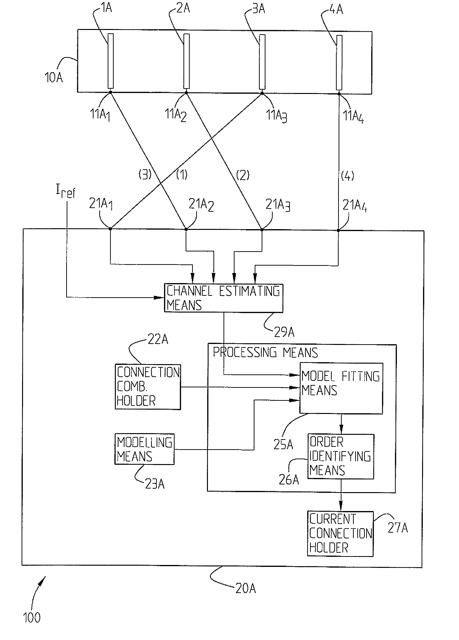
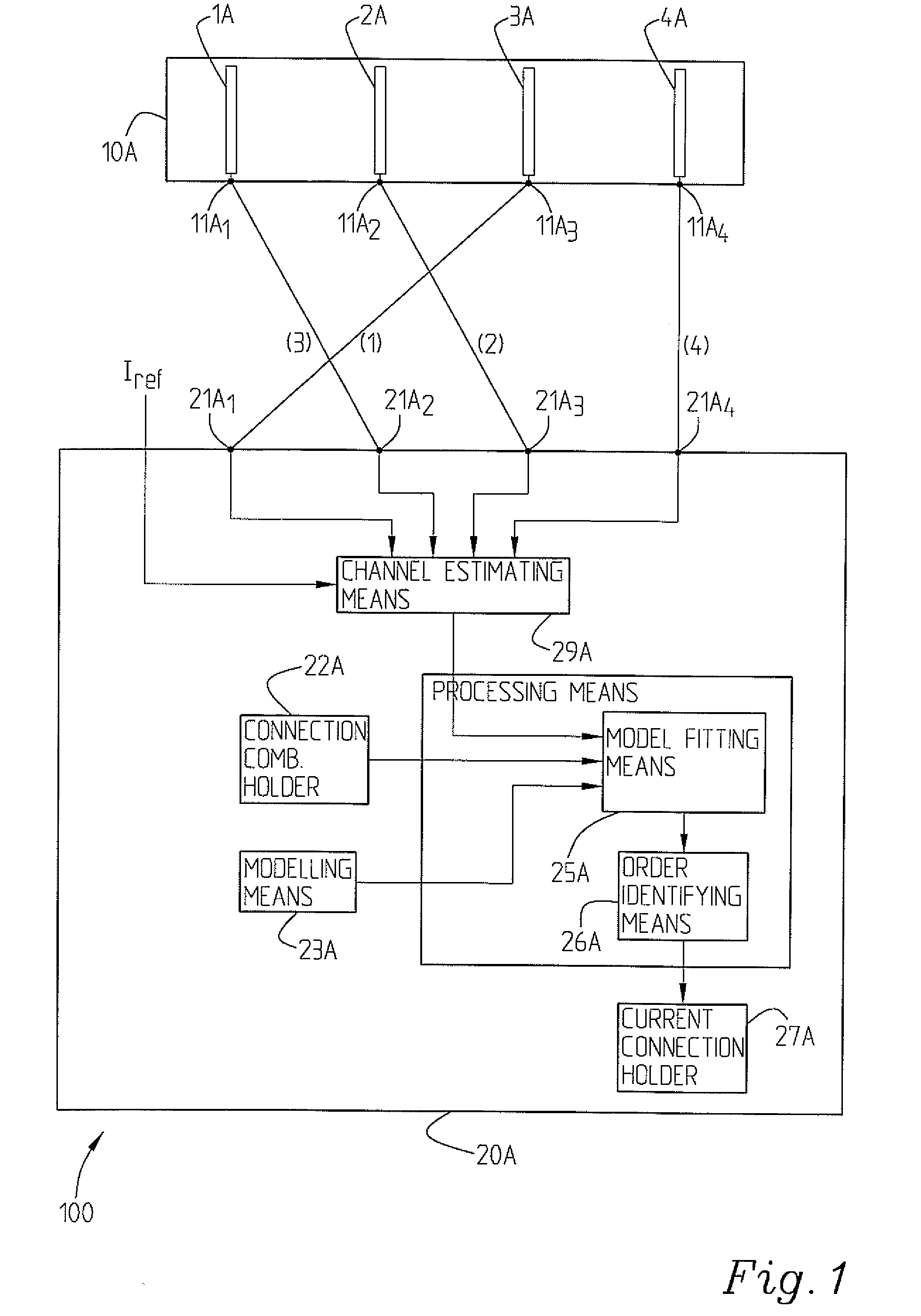
[0017]FIG. 1 is a block diagram showing a first examplary embodiment of a wireless communication node 20A according to the present invention. It is adapted to be connected to or comprises an antenna part 10A with a plurality of antenna elements 1A, 2A, 3A, 4A which here are of the same polarization. It should be clear that the invention is not limited to wireless communication nodes adapted to be connected to or comprising an antenna part with four antenna elements. FIG. 1 merely relates to a particular example. In practise it could be somewhat fewer antenna elements as well as considerably more antenna elements, particularly since the problems intended to be solved by the present invention tend to become more complicated and serious the more antenna elements on the antenna part.

[0018]Each antenna element is connected to an antenna port 11A1, 11A2, 11A3, 11A4. The antenna elements 1A, 2A, 3A, 4A are connected by means of feeder cables to feeder ports 21A1, 21A2, 21A3, 21A4. In this ...


PUM


Abstract

The present invention relates to a wireless communication node (20A) adapted to via feeder ports be connected to antenna ports. It comprises signal handling and estimating means (21A) adapted to collect signals from a mobile station and to generate a plurality of channel estimates, connection combination information holding means (22A) adapted to hold information about all possible feeder port-antenna port connections, processing means (24A) comprising channel modelling means (23A) adapted to provide a channel model for the received signals. If further comprises channel model fitting means (25A) adapted to compare the channel model with the channel estimates for a plurality of permutations obtained by the connection combination information and order identifying means (26A) adapted to identify the feeder port connection order corresponding to the permutation order giving the best fit between channel model and channel estimates, hence allowing identification of the order in which the feeder ports actually are connected to the antenna ports.

Description

TECHNICAL FIELD[0001]The present invention relates to a wireless communication node being adapted to be connected to or comprising an antenna part with a plurality of antenna elements with respective antenna ports to which feeder port of the wireless communication node are connected. The antenna ports are associated with unique antenna port identifications and the feeder ports are associated with respective unique feeder port identifications. The invention also relates to a method for in such a node determining which antenna ports actually are connected to which feeder ports.BACKGROUND[0002]For antenna arrangments comprising a plurality antenna elements, for example array antenna systems, it is in many cases important to know which antenna ports actually are connected to which feeder ports, i.e. to which radio chains. This means not only the way they should have been connected, but the way they actually have been connected. It is of most importance that they are connected in a speci...

Claims


Application Information

Patent Timeline
Patent Type & Authority Applications(United States)
IPC IPC(8): H04B1/10
CPCH01Q21/06H04B17/20H04B17/10H04B7/04H04B17/0002H04B17/004
Inventor COLDREY, MIKAELATHLEY, FREDRIKPETERSON, SVEN OSCAR
Owner TELEFON AB LM ERICSSON (PUBL)
Why Eureka
Try Eureka