Annular spring element for a hydraulic belt tensioner

a technology of annular filter element and hydraulic belt tensioner, which is applied in the direction of servomotor components, fluid-pressure actuators, servomotors, etc., can solve the problems of increased manufacturing and the risk of developing disadvantageous noise, and achieve the optimal switching hysteresis of the annular filter element, improve the operating behavior, and fast responsiveness

Inactive Publication Date: 2012-04-19
SCHAEFFLER TECH AG & CO KG
View PDF37 Cites 3 Cited by
  • Summary
  • Abstract
  • Description
  • Claims
  • Application Information

AI Technical Summary

Benefits of technology

[0010]The design according to the invention allows the hydraulic tensioning system to be adapted in an improved way to the actual demands. The necessary adaptation to actual engine dynamics can be performed easily with the proposed design, which leads to an overall improved operating behavior compared with prior solutions.
[0011]Other advantageous constructions of the invention are the subject matter of the dependent claims 2 to 10.
[0012]One preferred design of the invention provides that, for forming the annular spring valve, the cylinder has, in the area of the pressure chamber, at least one opening that interacts with a spring element enclosing the cylinder on the outside and biased in the closing direction. The spring element guided on the cylinder on the outside generates, until reaching an opening pressure, an effective seal for the opening and thus prevents a flow or an exchange of hydraulic fluid from the pressure chamber into the storage chamber.
[0013]Advantageously, the cylinder includes, in one plane, several openings that are positioned distributed around the periphery and are effectively closed by the spring element in a neutral position of the piston or until reaching an opening pressure.
[0014]According to the invention, it is possible to create a hydraulic tensioning system in which the piston-cylinder unit comprises a first annular spring valve designed as a one-way valve and allocated to the outflow path, as well as a second conventional one-way valve designed as a ball valve and allocated to the inflow path.
[0015]The spring element of the annular spring element is preferably positioned in an annular groove expanded in a V-shape on the outside of the cylinder. A desired fast responsiveness, i.e., optimal switching hysteresis of the annular filter element, is achieved in that the spring element interacts with several relatively large openings of the cylinder, wherein the hydraulic pressure in the pressure chamber of the piston-cylinder unit impinges on a large surface area of the annular element. An increased depth of the annular groove further improves the switching hysteresis, because an increased control path of the spring element guarantees, in the case of an overpressure of the hydraulic fluid in the pressure chamber, a nearly resistance-free flow of the hydraulic fluid.

Problems solved by technology

The valve is supported not over its entire surface in the installation state which can lead to an instable position of the valve body, with the risk of developing disadvantageous noise.
The structural configuration includes at least three individual parts that are required for completing the non-return valve and that require a complicated manufacturing process and handling for assembly.
A leakage gap that directly influences the damping of the tensioning system and is arranged between the lateral surface of the piston and the inner wall of the cylinder represents an increased manufacturing expense, in order to realize an installation play for a defined leakage gap.

Method used


Image

  • Annular spring element for a hydraulic belt tensioner
  • Annular spring element for a hydraulic belt tensioner
  • Annular spring element for a hydraulic belt tensioner

Examples


Embodiment Construction

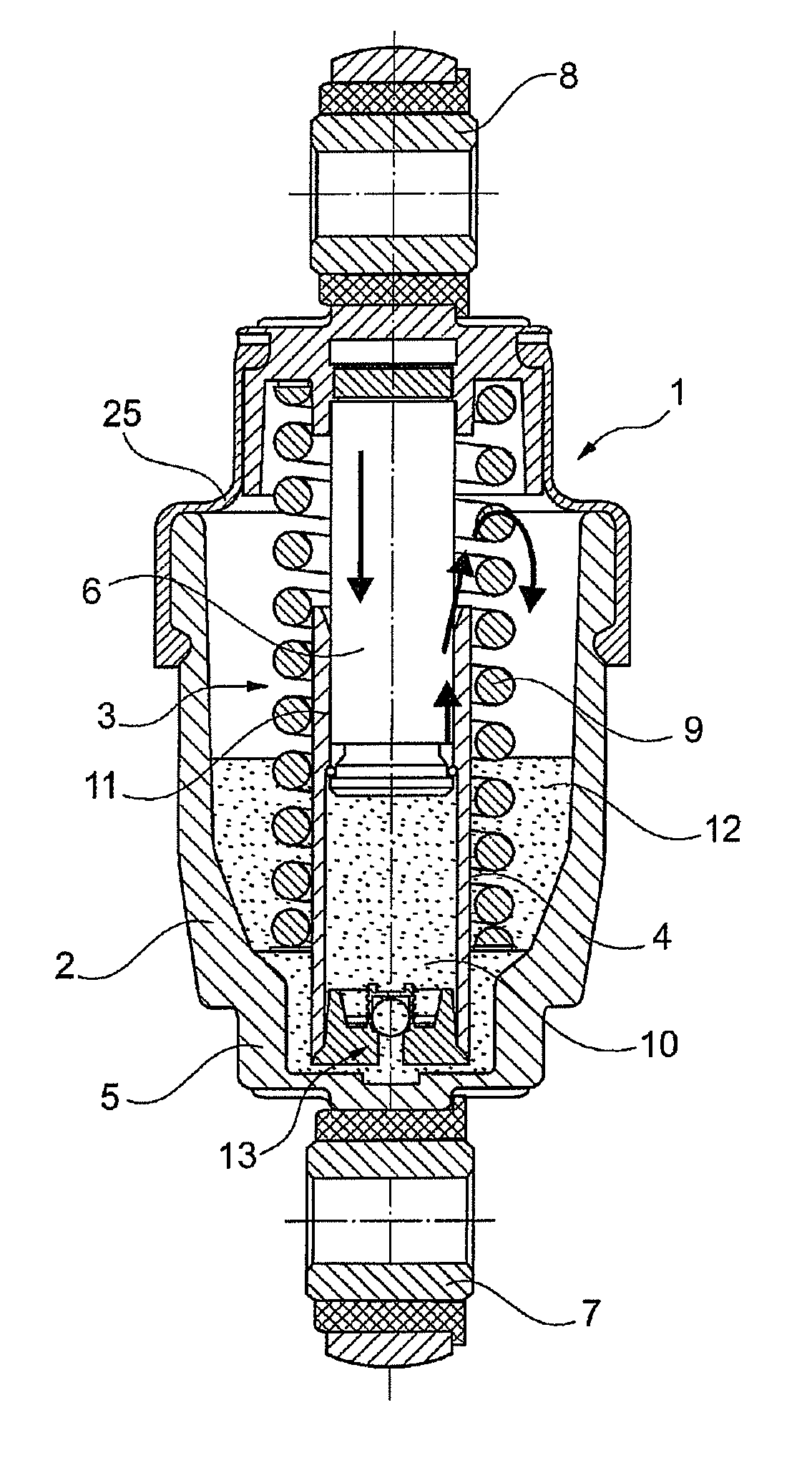
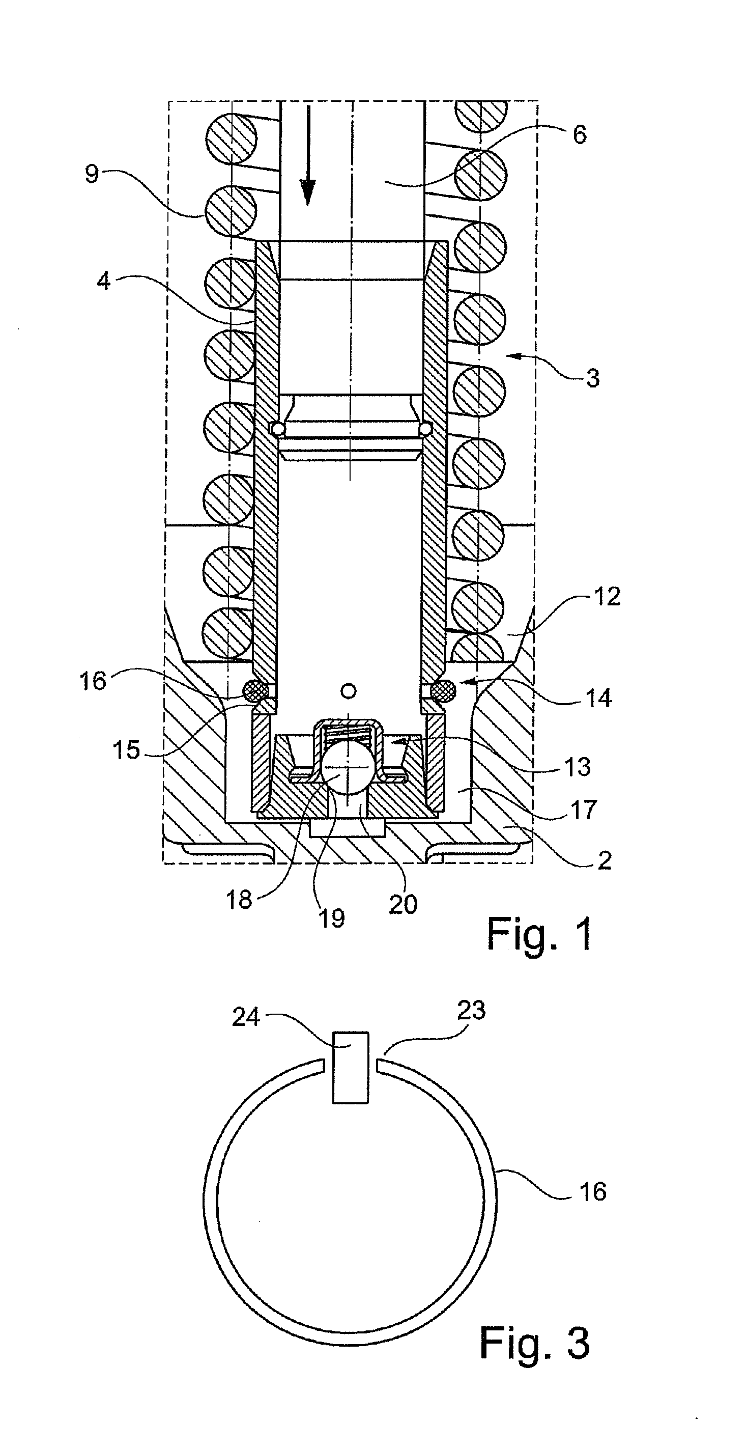
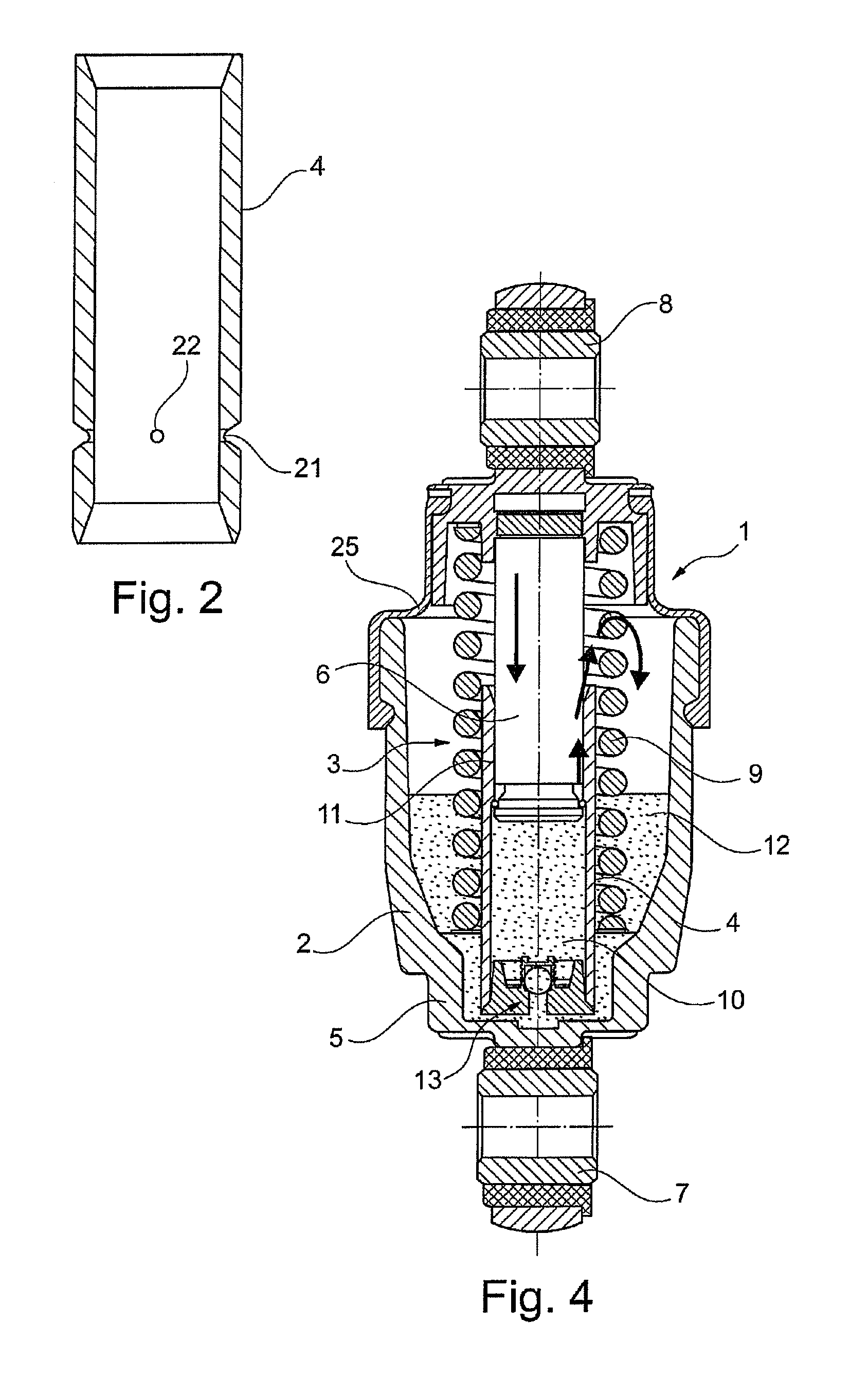
[0025]The description of a known hydraulic tensioning system 1 follows according to FIG. 4. The design of the tensioning system 1 comprises a pot-shaped housing 2 in which a piston-cylinder unit 3 is inserted in the center. A cylinder 4 is fixed in position in a base 5 of the piston-cylinder unit 3 and is designed for holding a piston 6 displaceable in the cylinder 4. Both the housing 2 and also the piston 6 have a fastening eye 7, 8 by means of which the tensioning system 1 is fixed in the operating state. A compression spring 9 inserted between the base 5 of the housing 2 and the piston 6 generates a spreading force that tensions a belt in a belt drive, for example, in connection with a tensioning roller allocated indirectly to the tensioning system 1 and not shown in FIG. 4. The cylinder 4 and the piston 6 of the piston-cylinder unit 3 define a pressure chamber 10 filled with a hydraulic fluid. For a control motion of the piston 6 in the direction of the arrow, this motion is dam...


PUM


Abstract

A hydraulic tensioning system (1) for a belt drive, including a cylinder (4) that is designed to receive a linearly displaceable piston (6), these elements together forming a piston-cylinder unit (3) and delimiting a pressure chamber (10) that is filled with hydraulic fluid. A relative movement between the piston (6) and the cylinder (4) causes the hydraulic fluid to be exchanged between the pressure chamber (10) and a storage chamber (12) or vice versa. At least one annular spring valve (14), which opens depending on the pressure, is positioned in an outflow section (17) for the hydraulic fluid between the pressure chamber (10) and the storage chamber (12) as a one-way valve.

Description

BACKGROUND[0001]The invention relates to a hydraulic tensioning system of a belt drive, with this system comprising a pot-shaped housing forming a cylinder for holding a linearly displaceable piston, which together form a piston-cylinder unit and delimit a pressure chamber filled with hydraulic fluid, wherein a relative movement between the piston and the cylinder triggers an exchange of the hydraulic fluid from the pressure chamber into a storage chamber or vice versa.[0002]The hydraulic tensioning systems used in belt drives of internal combustion engines must have a quick response, in order to always guarantee sufficient biasing tension and damping in all operating states and in the event of high-frequency belt oscillations. In order to satisfy this demand, the non-return valves integrated in hydraulic tensioning systems must be designed so that, after a compensation of the hydraulic fluid via a leakage gap into the storage chamber, in which damping is generated by the shear forc...

Claims


Application Information

Patent Timeline
Patent Type & Authority Applications(United States)
IPC IPC(8): F16H7/08F15B11/10
CPCF16H7/0836F16H7/0848F16H2007/0891F16H2007/0812F16H2007/0859F16H2007/0806
Inventor KOWALSKI, MARCO
Owner SCHAEFFLER TECH AG & CO KG
Why Eureka
Try Eureka