Press load controlling apparatus for mechanical press

a technology of mechanical presses and control apparatuses, which is applied in the direction of presses, press rams, manufacturing tools, etc., can solve the problems of die and machine breaking, overload, and the press (shaping) load acting on the die is too small to shape a satisfactory product, etc., to achieve the effect of suppressing breakthrough phenomena, prolonging pressure-application time in the vicinity of the bottom dead center, and high responsiveness

Inactive Publication Date: 2012-04-19
AIDA ENG LTD
View PDF9 Cites 17 Cited by
  • Summary
  • Abstract
  • Description
  • Claims
  • Application Information

AI Technical Summary

Benefits of technology

[0036]According to the presently disclosed subject matter, the pressure of the hydraulic pressure chamber of the cylinder-piston mechanism provided in the slide of the mechanical press can be variably controlled with a high responsiveness, and hence the following effects can be obtained. That is, even if the die height value is set to a value small enough to cause an overload, the press load can be restricted before the occurrence of the overload, and this can save the trouble of strictly adjusting the die height value. Further, the pressure-application time in the vicinity of the bottom dead center can be lengthened, and the breakthrough phenomenon can be suppressed from occurring at the end of pressure application. Still further, because the overload does not occur, the pressure liquid in the hydraulic pressure chamber of the cylinder-piston mechanism is not relieved, so that the interruption of the press operation is avoided.

Problems solved by technology

If the die height value is not strictly adjusted and the die height value is excessively small, a die and a product sandwiched between a press slide and a bolster, eventually, the press machine itself is subjected to an overload due to (an action for elastic recovery from) elastic deformation of the machine (including a column and an in-slide cylinder / hydraulic pressure chamber), so that the die and the machine are broken.
Conversely, if the die height value is excessively large, the press (shaping) load acting on the die is too small to shape a satisfactory product.
Similarly to the problem (1), if the die height value is set to be small, the overload occurs.

Method used


Image

  • Press load controlling apparatus for mechanical press
  • Press load controlling apparatus for mechanical press
  • Press load controlling apparatus for mechanical press

Examples


first embodiment

Configuration of Press Load Controlling Apparatus for Mechanical Press (First Embodiment)
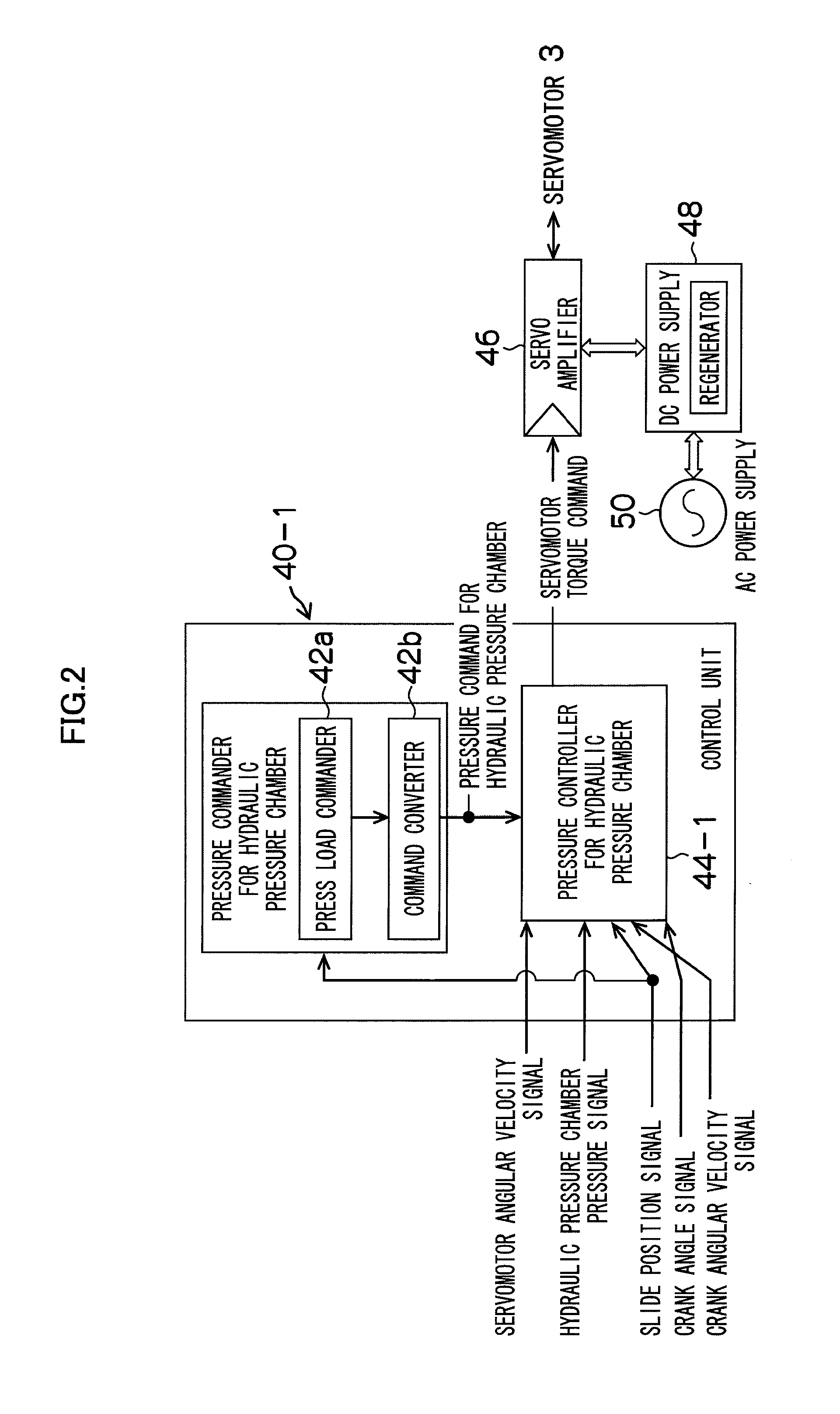
[0050]

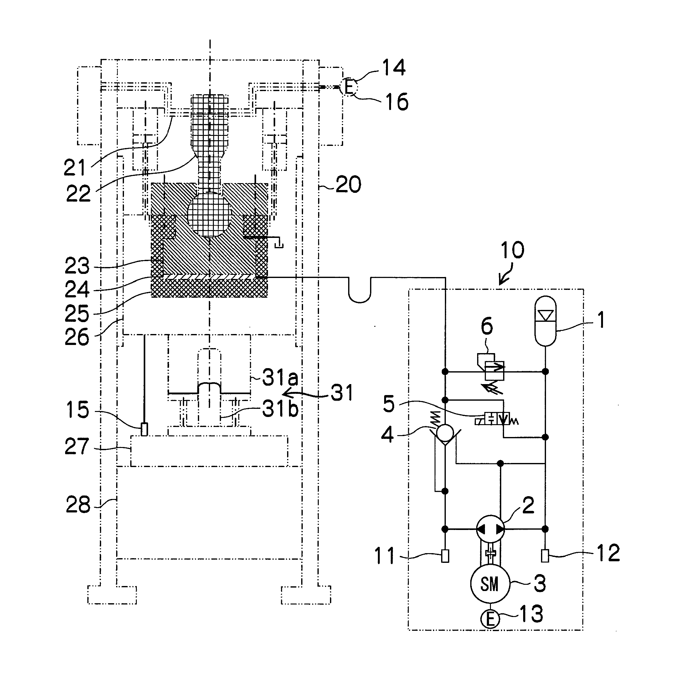
[0051]FIG. 1 is a configuration diagram illustrating a first embodiment of the press load controlling apparatus for the mechanical press according to the presently disclosed subject matter.

[0052]The mechanical press illustrated in FIG. 1 includes a column (frame) 20, a slide 26, and a bolster 27 placed on a bed 28, and the slide 26 is movably guided in the vertical direction by a guide unit provided to the column 20. The slide 26 is moved by a crank mechanism in the top-bottom direction of FIG. 1, and the crank mechanism includes: a crankshaft 21 to which a rotary driving force is transmitted by a driving device (not illustrated); a connecting rod 22; and a cylinder-piston mechanism provided in the slide 26 (an in-slide cylinder 25 and an in-slide piston 23). Note that, reference numeral 24 designates a hydraulic pressure chamber of the cylinder-piston mechanism.

[0053]A slide position dete...

second embodiment

Configuration of Press Load Controlling Apparatus for Mechanical Press (Second Embodiment)

[0110]FIG. 5 is a configuration diagram illustrating a second embodiment of the press load controlling apparatus for the mechanical press according to the presently disclosed subject matter. FIG. 6 is a block diagram illustrating a control unit in the press load controlling apparatus for the mechanical press according to the second embodiment.

[0111]The press load controlling apparatus for the mechanical press according to the second embodiment illustrated in FIG. 5 and FIG. 6 is different mainly in that a hydraulic circuit 10-2 and a control unit 40-2 are provided instead of the hydraulic circuit 10 and the control it 40-1 in the press load controlling apparatus according to the first embodiment illustrated in FIG. 1 and FIG. 2. Note that, in FIG. 5 and FIG. 6, elements common to those of the first embodiment illustrated in FIG. 1 and FIG. 2 are designated by the same reference numerals and cha...

third embodiment

Configuration of Press Load Controlling Apparatus for Mechanical Press (Third Embodiment)

[0118]FIG. 7 is a configuration diagram illustrating a third embodiment of the press load controlling apparatus for the mechanical press according to the presently disclosed subject matter. FIG. 8 is a block diagram illustrating a control unit in the press load controlling apparatus for the mechanical press according to the third embodiment.

[0119]The press load controlling apparatus for the mechanical press according to the third embodiment illustrated in FIG. 7 and FIG. 8 is different from one system of the press load controlling apparatus according to the first embodiment illustrated in FIG. 1 and FIG. 2 mainly in that two systems of the press load controlling apparatus are left-right symmetrically provided.

[0120]Note that, in FIG. 7, elements common to those of the first embodiment illustrated in FIG. 1 are designated by the same reference numerals, and detailed description thereof will be om...


PUM


Abstract

In a mechanical press, the pressure (cylinder force) of a hydraulic pressure chamber of a cylinder-piston mechanism provided in a slide of the mechanical press can be variably controlled with a high responsiveness by a hydraulic pump/motor driven by an electric servomotor, in response to a cylinder force command corresponding to the press load command. Accordingly, even if a die height value is set to a value small enough to cause an overload, the press load can be restricted before the occurrence of the overload, and this can save the trouble of strictly adjusting the die height value. Further, pressure-application time in the vicinity of a bottom dead center can be lengthened, and a breakthrough phenomenon can be suppressed from occurring at the end of pressure application. Still further, because the overload does not occur, pressure oil is not relieved, so that the interruption of a press operation is avoided.

Description

BACKGROUND OF THE INVENTION[0001]1. Field of the Invention[0002]The presently disclosed subject matter relates to a press load controlling apparatus for a mechanical press driven by a crank or a linkage mechanism, and more particularly, to a technique of controlling a press load by a cylinder-piston mechanism provided in a slide of a mechanical press.[0003]2. Description of the Related Art[0004]Up to now, mechanical presses of this type have been described in Japanese Patent Application Laid-Open Nos. 2001-1199, 08-118083, and 06-155088.[0005]An overload preventing apparatus for a mechanical press described in Japanese Patent Application Laid-Open No. 2001-1199 is provided with a hydraulic pressure chamber for overload absorption in a slide of the mechanical press, and is also provided with an overload preventing valve that performs a relief operation when the pressure of the hydraulic pressure chamber exceeds a set overload pressure. The overload preventing valve is provided with a...

Claims


Application Information

Patent Timeline
Patent Type & Authority Applications(United States)
IPC IPC(8): B30B15/14
CPCB30B15/284B30B1/265
Inventor KOHNO, YASUYUKIKONDO, TADAHIROMAKABE, JUNJIYAMANOUCHI, AKIRA
Owner AIDA ENG LTD
Why Eureka
Try Eureka