Optical imaging lens assembly

Active Publication Date: 2012-04-19
LARGAN PRECISION
View PDF2 Cites 49 Cited by
  • Summary
  • Abstract
  • Description
  • Claims
  • Application Information

AI Technical Summary

Benefits of technology

[0010]By such arrangement, photosensitivity and total track length of the optical imaging lens assembly can be reduced, and the aberration and astigmatism of the assembly can be effectively corrected. Moreover, high image resolution can be obtained.
[0011]In the aforementioned optical imaging lens assembly, the first lens element has positive refractive power and thereby can provide the main refractive power that the assembly needs, which is favorable for reducing the total track length of the optical imaging lens assembly. The second lens element has negative refractive power, and thereby the aberration produced by the first lens element can be effectively corrected and the chromatic aberration of the system can be favorably corrected in the same time. The third lens element has negative refractive power and thereby can cooperate with the second lens element for aberration correction, chromatic aberration correction and reducing the sensitivity of the assembly. The fourth lens element has negative refractive power, and thereby the Petzval Sum of the assembly can be favorably corrected so that enabling the peripheral image plane to become flatter. When the fifth lens element has positive refractive power, the total optical track length of the assembly can be favorably reduced and thereby keeping the lens compact.
[0012]In the aforementioned optical imaging lens assembly, the first lens element may be a bi-convex lens element or a meniscus lens element having a convex object-side surface and a concave image-side surface; when the f

Problems solved by technology

However, due to the popularity of high standard mobile devices such as smart phones and PDAs (Personal Digital Assistant) driving the rapid improvements in high r

Method used


Image

  • Optical imaging lens assembly
  • Optical imaging lens assembly
  • Optical imaging lens assembly

Examples


Example

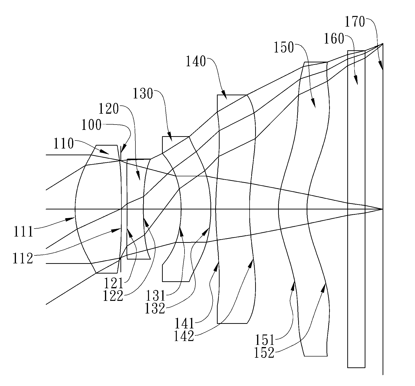
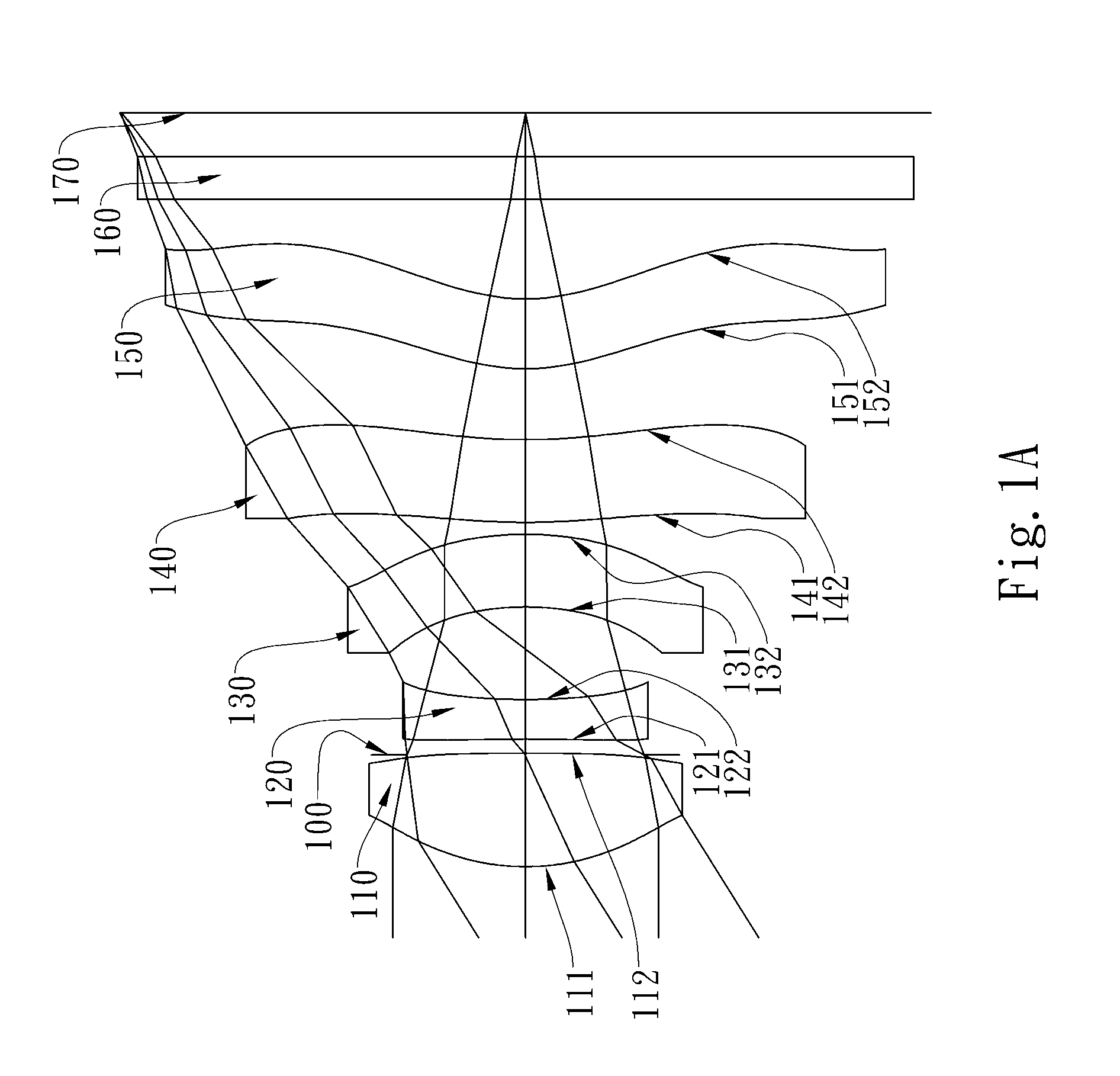
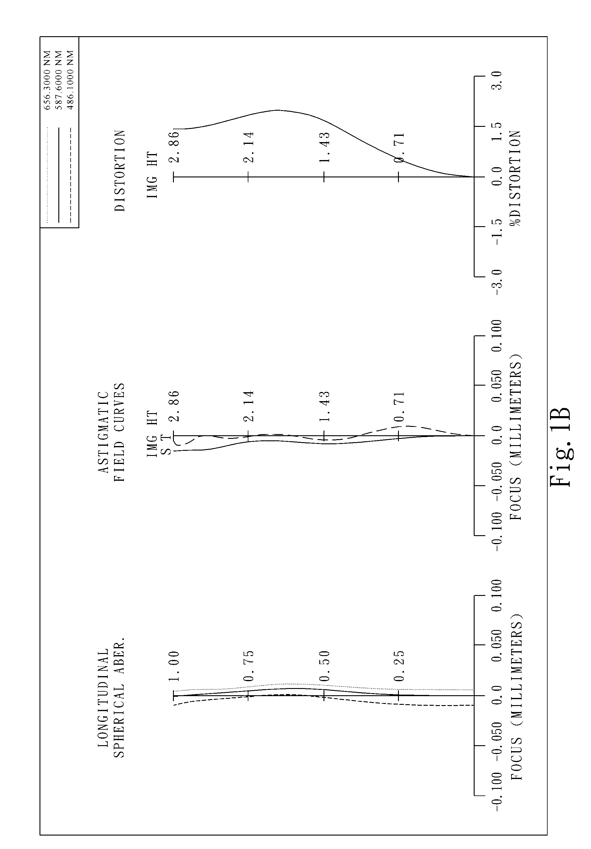
[0079]FIG. 1A shows an optical imaging lens assembly in accordance with the first embodiment of the present invention, and FIG. 1B shows the aberration curves of the first embodiment of the present invention. The optical imaging lens assembly of the first embodiment of the present invention mainly comprises five lens elements, in order from an object side to an image side:

[0080]a plastic first lens element 110 with positive refractive power having a convex object-side surface 111 and a convex image-side surface 112, the object-side and image-side surfaces 111 and 112 thereof being aspheric;

[0081]a plastic second lens element 120 with negative refractive power having a concave object-side surface 121 and a concave image-side surface 122, the object-side and image-side surfaces 121 and 122 thereof being aspheric;

[0082]a plastic third lens element 130 with negative refractive power having a concave object-side surface 131 and a convex image-side surface 132, the object-side and image-s...

Example

[0109]FIG. 2A shows an optical imaging lens assembly in accordance with the second embodiment of the present invention, and FIG. 2B shows the aberration curves of the second embodiment of the present invention. The optical imaging lens assembly of the second embodiment of the present invention mainly comprises five lens elements, in order from an object side to an image side:

[0110]a plastic first lens element 210 with positive refractive power having a convex object-side surface 211 and a concave image-side surface 212, the object-side and image-side surfaces 211 and 212 thereof being aspheric;

[0111]a plastic second lens element 220 with negative refractive power having a convex object-side surface 221 and a concave image-side surface 222, the object-side and image-side surfaces 221 and 222 thereof being aspheric;

[0112]a plastic third lens element 230 with negative refractive power having a concave object-side surface 231 and a convex image-side surface 232, the object-side and imag...

Example

[0135]FIG. 3A shows an optical imaging lens assembly in accordance with the third embodiment of the present invention, and FIG. 3B shows the aberration curves of the third embodiment of the present invention. The optical imaging lens assembly of the third embodiment of the present invention mainly comprises five lens elements, in order from an object side to an image side:

[0136]a plastic first lens element 310 with positive refractive power having a convex object-side surface 311 and a concave image-side surface 312, the object-side and image-side surfaces 311 and 312 thereof being aspheric;

[0137]a plastic second lens element 320 with negative refractive power having a concave object-side surface 321 and a concave image-side surface 322, the object-side and image-side surfaces 321 and 322 thereof being aspheric;

[0138]a plastic third lens element 330 with negative refractive power having a convex object-side surface 331 and a concave image-side surface 332, the object-side and image-...


PUM


Abstract

This invention provides an optical imaging lens assembly comprising five lens elements with refractive power, in order from an object side to an image side: a first lens element with positive refractive power having a convex object-side surface; a second lens element with negative refractive power; a third lens element with negative refractive power; a fourth lens element with negative refractive power having at least one of the object-side and image-side surfaces thereof being aspheric; and a fifth lens element having a concave image-side surface, at least one of the object-side and image-side surfaces thereof being aspheric, and made of plastic. By such arrangement, photosensitivity and total track length of the optical imaging lens assembly can be reduced, and the aberration and astigmatism of the assembly can be effectively corrected. Moreover, high image resolution can be obtained.

Description

CROSS-REFERENCE TO RELATED APPLICATIONS[0001]This non-provisional application claims priority under 35 U.S.C. §119(a) on Patent Application No. 099135183 filed in Taiwan, R.O.C. on Oct. 15, 2010, the entire contents of which are hereby incorporated by reference.BACKGROUND OF THE INVENTION[0002]1. Field of the Invention[0003]The present invention relates to an optical imaging lens assembly, and more particularly, to a compact optical imaging lens assembly used in an electronic product.[0004]2. Description of the Prior Art[0005]The demand for compact imaging lens assembly has grown in recent years as the popularity of portable electronic products with the photographing function has increased. The sensor of a general photographing camera is none other than CCD (Charge Coupled Device) or CMOS (Complementary Metal Oxide Semiconductor Sensor). Furthermore, as advanced semiconductor manufacturing technology has allowed the pixel size of sensors to be reduced, and the resolution of compact ...

Claims


Application Information

Patent Timeline
IPC IPC(8): G02B13/18
CPCG02B13/0045
Inventor TSAI, TSUNG HANHUANG, HSIN HSUAN
Owner LARGAN PRECISION
Why Eureka
Try Eureka