
Projection headlight for motor vehicles

a technology for driving vehicles and headlights, which is applied in the direction of vehicle components, signalling/lighting devices, optical signalling, etc., can solve the problems of relatively high cost of changing led light sources in this way, and achieve the effects of simplifying assembly, simplifying electrical contact arrangements, and reducing the number of components

Inactive Publication Date: 2012-04-19
HELLA KG HUECK & CO
View PDF21 Cites 19 Cited by
  • Summary
  • Abstract
  • Description
  • Claims
  • Application Information

AI Technical Summary

Benefits of technology

[0009]The special advantage of the invention consists in the fact that in the preparation of the light stream, only a single light source carrier is necessary on which the light sources are arranged. Only a single heat sink must be assigned to the light source carrier. In this way the number of components is reduced, which leads to a simplified assembly and in particular to simplification of the electrical contact arrangements. In this way, since the light source carrier is attached to the heat sink, in cases of repair access to the light sources is achieved simply by detaching the heat sink.
[0010]According to a preferred embodiment of the invention, the light source carrier, the reflector device, and the heat sink form a common exchangeable modular unit, which is attached in a way that it can be detached from the frame that receives the cover and / or the lens device. Preferentially, in this way the exchangeable modular unit can be removed relatively simply from the projection headlight, so that for example in case of repair the light sources can be changed. The heat sink may have a form that supports the natural convection of the heated air. The heat sink can be set up in this relative space-saving manner.
[0011]According to a further embodiment of the invention, the cover and the lens device are arranged on a front side of the adjustable frame, and the reflector device and the light source device are arranged on a back side of the adjustable frame. It is advantageous here to have a basically constructed assembly of the projection headlight enabled, something that reduces the assembly expenditure.
[0012]According to a further embodiment of the invention, the light source switch carrier is created rigid and extends on a plane. It is advantageous in this way to support a simple adjustment of the reflector to various light source switch carriers. Further advantages of the invention result from the other dependent claims.
[0013]Further areas of applicability of the present invention will become apparent from the detailed description provided hereinafter. It should be understood that the detailed description and specific examples, while indicating the preferred embodiment of the invention, are intended for purposes of illustration only and are not intended to limit scope of the invention.

Problems solved by technology

Changing the LED light sources in this way is relatively expensive.

Method used


Image

  • Projection headlight for motor vehicles
  • Projection headlight for motor vehicles
  • Projection headlight for motor vehicles

Examples


Embodiment Construction

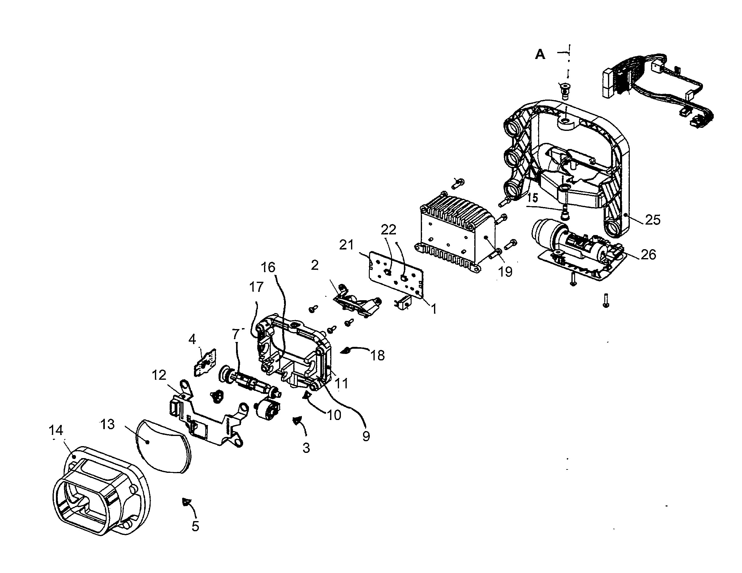
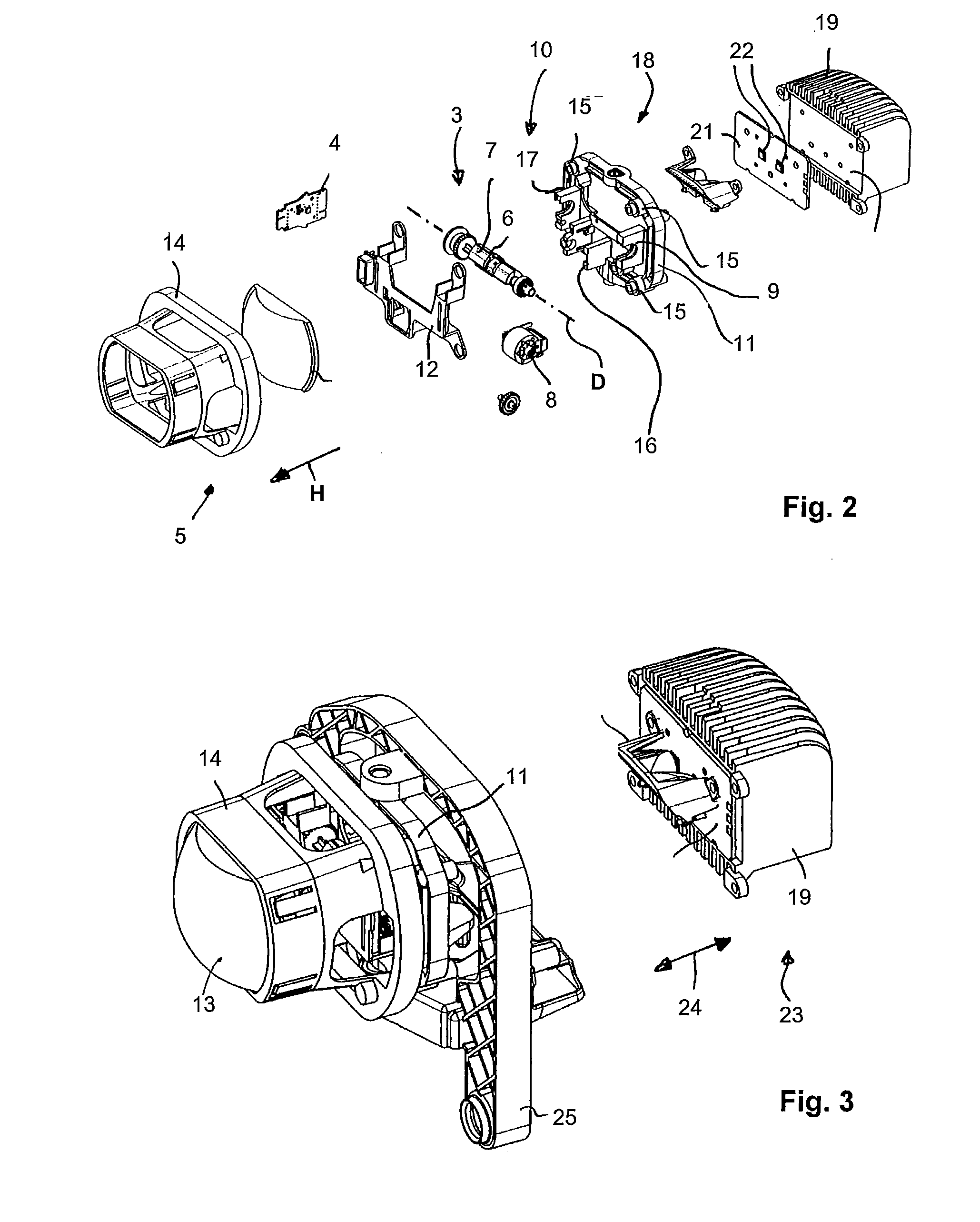
[0019]A projection headlight for motor vehicles essentially consists of a light source device 1, a reflector device 2, a cover 3, and a lens device 5 arranged in the main radiation direction H in front of these devices.

[0020]The cover 3 is arranged in the area of a focal point of the lens device 5 and permits the projection of cut-off lines of various light diffusions (light figures) through the arrangement of several glare edges 6. For this, several glare edges 6 run in the lengthwise direction of a cover shaft 7 of the cover 3, whereby the cover shaft 7 is rotatable around a rotating axis D in the various activation turn positions by means of an electric motor 8.

[0021]The cover shaft 7 is stored in receptacles 9 on a front side 10 of an adjustable frame 11. A lower area of the front side 10 is covered by a covering element 12, which is fastened like a lens holder 14 bearing a lens 13, preferably detachable at the edge side attachment points 15 of the adjustable frame 11.

[0022]On t...


PUM


Abstract

A projection headlight for motor vehicles has a reflector device, a plurality of light sources, at least one of said light sources assigned to the reflector device. A lens device is arranged in front of the reflector device in the main radiation direction. A cover device in the area of a focal point of the lens device has a cover shaft rotatable across the main radiation direction of the rotating axis main source. The cover shaft is provided with a number of glare edges and / or glare surfaces to adjust light distributors having a number of various cut-off lines. The light sources are arranged on a common light source carrier, the carrier extending substantially perpendicular to the main radiation direction and the carrier being configured to fasten onto a flat side of a heat sink.

Description

RELATED APPLICATIONS[0001]This application claims priority and benefit of German Patent Application No. 102010045435.4, filed on Sep. 15, 2010, all of which is incorporated herein by reference.BACKGROUND OF INVENTION[0002]1. Field of the Invention[0003]The invention involves a projection headlight for motor vehicles with a reflector device, with at least one light source device assigned to the reflector device, and which is provided with a number of light sources, with one lens device assigned to the major radiating direction in front of the reflector device and with a cover arranged in the area of a focal point of the lens device; the cover has a turnable cover shaft running across the major radiating direction of the rotation axis, in which the cover shaft is provided with a number of glare edges and / or glare surfaces for setting up light distributors having a number of various cut-off lines.[0004]2. Related Art[0005]A headlight for motor vehicles is known from U.S. 7,540,638 B2, ...

Claims


Application Information

Patent Timeline
Patent Type & Authority Applications(United States)
IPC IPC(8): B60Q1/04
CPCF21S48/1109F21S48/1154F21S48/321F21S48/1266F21S48/1794F21S48/1208F21S41/192F21S41/143F21S41/29F21S41/26F21S41/698F21S45/49F21S45/47
Inventor DIKAU, REINHARDCASTELLON, WILLIAMSUDAHL, JORGROTTINGER, AXELWULLER, MARTINSUSSELBECK, DANIELHOFMANNSCHWARZ, BASTIANBJORN, BLANKEGAUR, VIKRAMMIDDELBERG, BRIGITTERICKMEYER, HENDRIKSEIBT, SONJAZEHNER, SVEN
Owner HELLA KG HUECK & CO
Learn More