Reinforced Commissural Support Structure

a commissural support and reinforcement technology, applied in the field of reinforced commissural support structures, can solve the problems of stenosis, narrowing of the passageway through the valve, heart failure and ultimately death, and great discomfort, and achieve the effects of reducing the lifespan of the prosthetic valve, eliminating the tip deflection of the commissural points, and strengthening the commissural points of the wireform

Active Publication Date: 2012-04-19
EDWARDS LIFESCIENCES CORP
View PDF6 Cites 14 Cited by
  • Summary
  • Abstract
  • Description
  • Claims
  • Application Information

AI Technical Summary

Benefits of technology

[0010]The invention provides a solution to the aforementioned need to increase the lifespan of a prosthetic valve. The invention provides a device that reinforces the commissural points of a wireform without interfering with the function of the valve. The device of the invention is useable with a wide variety of valve designs, regardless of the stent or support structure that anchors the device to the vessel.
[0011]More specifically, the invention provides the wireform with a secondary, reinforcing component that act

Problems solved by technology

Such immobility also may lead to a narrowing, or stenosis, of the passageway through the valve.
The increased resistance to blood flow that a stenosed valve presents can eventually lead to heart failure and ultimately death.
Naturally, this is a heavily invasive procedure and inflicts great trauma on the body leading usually to great discomfort and considerable recovery time.
A v

Method used


Image

  • Reinforced Commissural Support Structure
  • Reinforced Commissural Support Structure
  • Reinforced Commissural Support Structure

Examples


Embodiment Construction

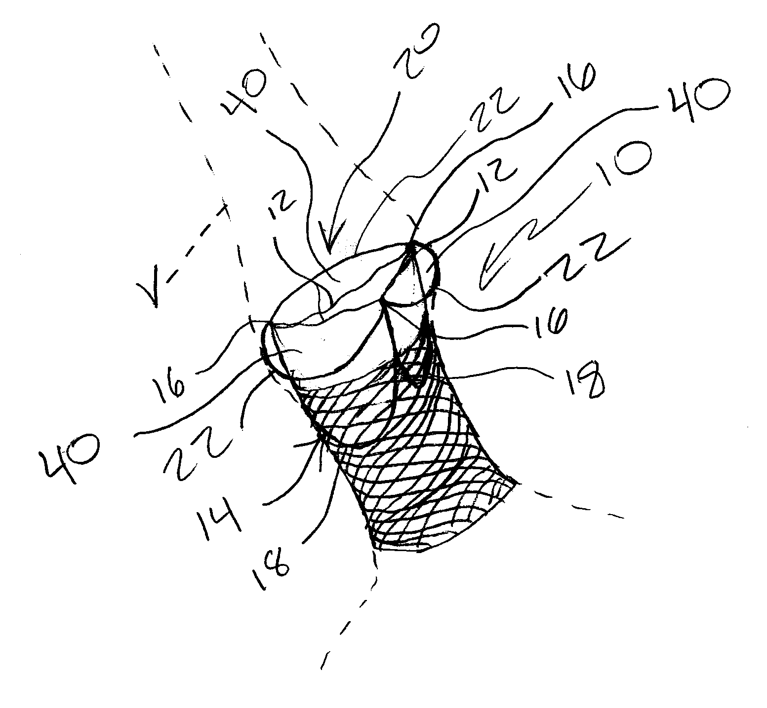
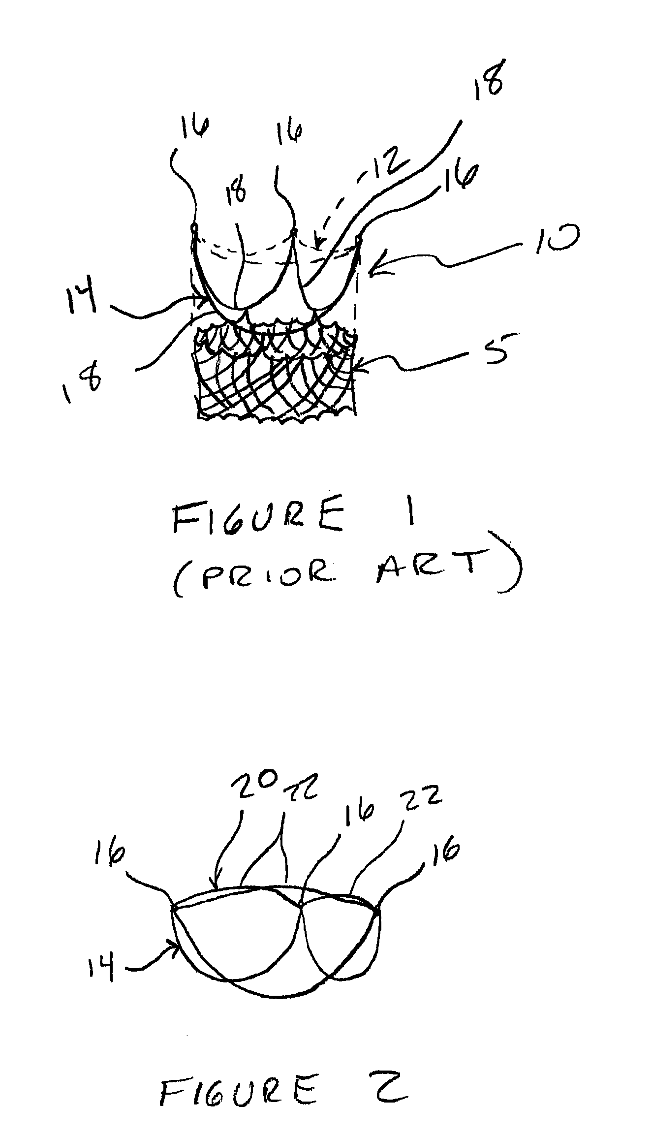
[0017]Referring now to the Figures and first to FIG. 1, there is shown a prior art prosthetic valve design that generally includes a support structure 5 and a valve 10. The support structure 5 is typically a stent or a mesh, braided tube made out of a material such as Nitinol.

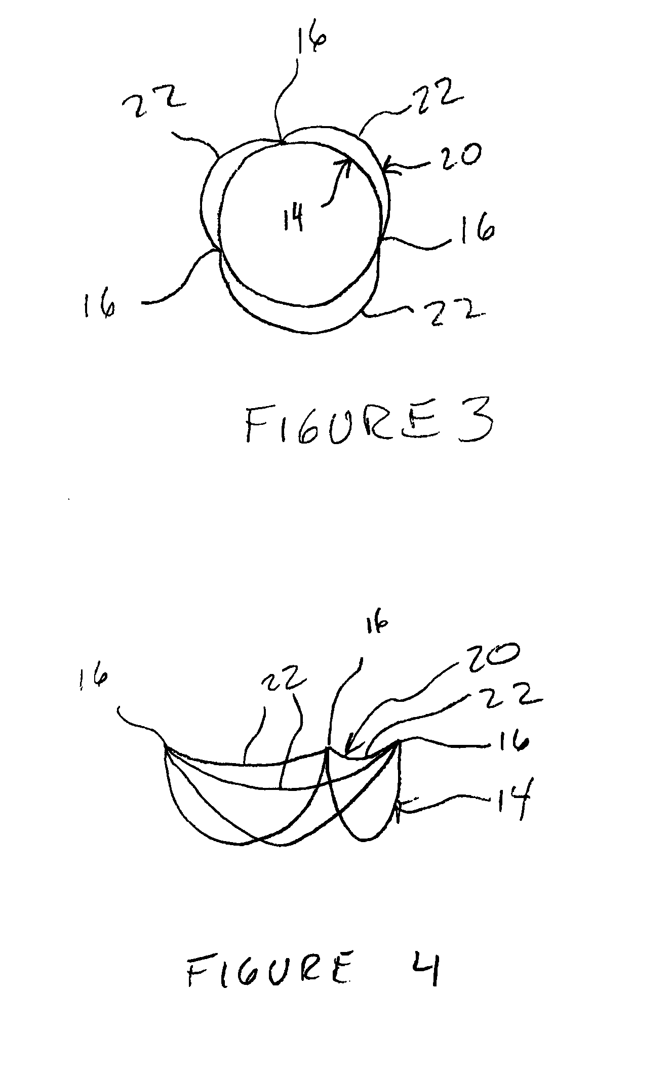
[0018]The valve 10 is constructed to mimic a native valve and generally comprises one or more sheets of porcine tissue 12 attached to a commissural wireform 14. The wireform 14 gives the tissue 12 the correct shape in order to form leaflets that coapt during diastole and separate during systole. The wireform 14 forms commissural points 16 separated by arcuate portions 18. The arcuate portions 18 are attached to the support structure 5. The commissural points 16 facilitate natural and efficient opening and closing of the valve 10.

[0019]The tissue 12 of the valve 10 is carefully sewn or otherwise attached to the wireform 14 such that, over time, the tissue does not tear or separate from the wireform 14. The tissu...


PUM


Abstract

A device and method for controlling commissural tip deflection of a prosthetic valve, thereby both preventing failure due to repeated movement and/or uneven loading of the commissural points and also improving coaptation of the valve leaflets, including connecting reinforcing material between the commissural points so a spring-like span is created across the points. The spanning material may be in the form of a ring that is lashed, sewn or otherwise connected to the commissural points. The reinforcing material may form curved segments between the commissural points that extend outwardly to form sinuses behind the leaflets of the prosthetic valve. The reinforcing material may also extend in an upstream direction to avoid interfering with blood flowing out of the prosthetic valve.

Description

RELATED APPLICATIONS[0001]This application claims priority to U.S. Provisional Patent Application Ser. No. 61 / 372,803 filed Aug. 11, 2010 entitled Reinforced Commissural Support to Gainor, the entirety of which is incorporated by reference herein. This application also incorporates by reference U.S. patent application Ser. No. 11 / 443,814 filed May 30, 2006 entitled Stentless Support Structure to Thill et al.BACKGROUND OF THE INVENTION[0002]There has been a significant movement toward developing and performing cardiovascular surgeries using a percutaneous approach. As used herein, the term “percutaneous” is defined as an alternative to a surgical approach whereby one or more catheters are introduced into the body via a small puncture, and typically into a body lumen, for example, the femoral artery. Through the one or more catheters, tools and devices can be delivered to a desired area, such as in the cardiovascular system, to perform any number of complicated procedures that normall...

Claims


Application Information

Patent Timeline
IPC IPC(8): A61F2/24
CPCA61F2/2418A61F2/2412
Inventor GAINOR, JOHN
Owner EDWARDS LIFESCIENCES CORP
Why Eureka
Try Eureka