Control Apparatus of a Direct Injection Gasoline Engine

a technology of control apparatus and gasoline engine, which is applied in the direction of electric control, machines/engines, output power, etc., can solve the problems of increasing the amount of pm emission during engine cold start, and increasing the amount of pm emission during acceleration operation. , to achieve the effect of reducing the amount of pm and pm emission, promoting fuel vaporization, and increasing fuel injection pressur

Inactive Publication Date: 2012-04-26
HITACHI AUTOMOTIVE SYST LTD
View PDF8 Cites 9 Cited by
  • Summary
  • Abstract
  • Description
  • Claims
  • Application Information

AI Technical Summary

Benefits of technology

[0009]With this structure, even in the case where response speed of the exhaust valve control is slow and it takes several cycles for an amount of internal EGR to reach a desired value (target value), the fuel pressure having high response speed is increased to atomize the fuel during the period until the amount of internal EGR reaches the desired value. Thereby, vaporization of the fuel is promoted, so that generation of PM and an amount of emission of PM can be suppressed.
[0010]Further, as another aspect of the control apparatus of the direct injection gasoline engine according to the present invention, wherein the engine includes a variable valve mechanism at an exhaust valve, the control apparatus is characterized in that it includes operation state determining means for determining operation state of a vehicle, and in that, when it is determined by the operation state determining means that the operation state of the vehicle is changed from constant speed operation or deceleration operation to acceleration operation, valve closing timing of the exhaust valve is advanced and fuel injection pressure is increased, and further range of increase in the fuel injection pressure is reduced in accompanying with the valve closing timing of the exhaust valve being advanced.
[0011]With this structure, by reducing range of increase in the fuel injection pressure in accompanying with the internal EGR approaching a desired value (target value), increase in drive force of a fuel pump due to increase in

Problems solved by technology

The direct injection gasoline engine has a problem that it has a larger amount of PM emission than an intake port injection type gasoline engine.
The causes of this problem are fuel adhesion to a cylinder and a piston due to direct injection of fuel into the cylinder, and existence of local fuel rich regions caused by insufficient mixing of fuel and air.
However, not only the amount of PM emission during engine cold start but also the amount of PM emission

Method used


Image

  • Control Apparatus of a Direct Injection Gasoline Engine
  • Control Apparatus of a Direct Injection Gasoline Engine
  • Control Apparatus of a Direct Injection Gasoline Engine

Examples


first embodiment

[0039]Hereinafter, configuration and operation of a control apparatus of a direct injection gasoline engine according to the present invention will be described with reference to FIG. 1 to FIG. 8.

[0040]First, configuration of a system, in which the control apparatus of the direct injection gasoline engine according to the present embodiment is applied to a gasoline engine for an automobile, will be described with reference to FIG. 1.

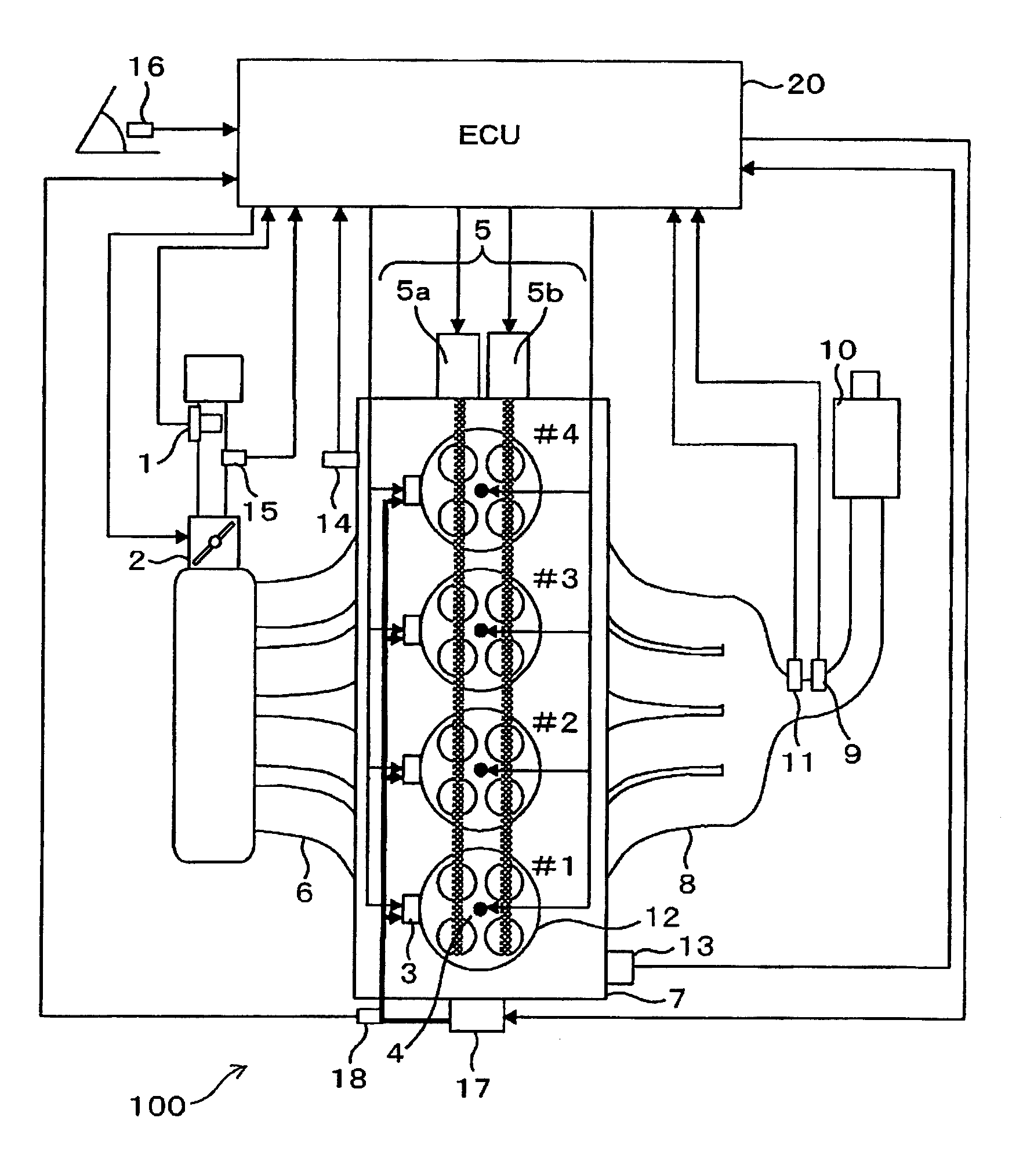
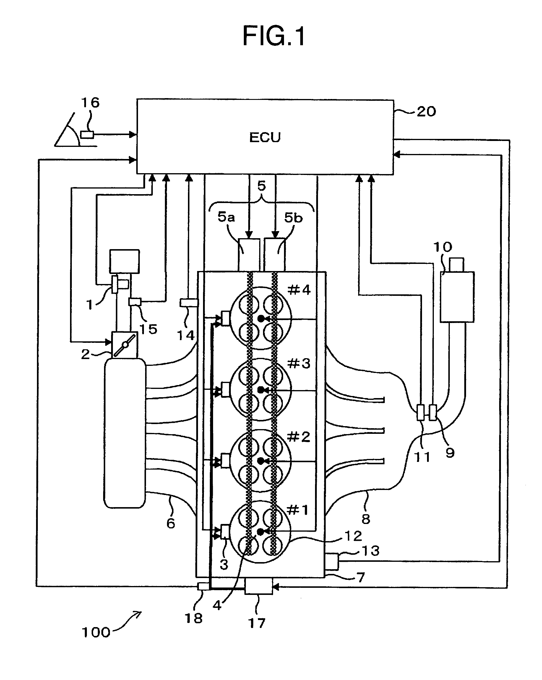
[0041]FIG. 1 is a view showing the configuration of the system in which the control apparatus of the direct injection gasoline engine according to a first embodiment of the present invention is applied to the gasoline engine for an automobile.

[0042]An engine 100 is a four-cylinder gasoline engine for an automobile, in which spark ignition combustion is carried out. An air flow sensor 1 which measures an intake air amount, an electronically-controlled throttle 2 which adjusts intake pipe pressure, and an intake air temperature sensor 15 which is a form of...

second embodiment

[0076]Next, structure and operation of a control apparatus of a direct injection gasoline engine according to the present invention will be described with reference to FIG. 9 to FIG. 14.

[0077]FIG. 9 is a view showing configuration of a system in which the control apparatus of a direct injection gasoline engine according to a second embodiment is applied to a multi-cylinder gasoline engine for an automobile. Instead of the variable valve 5 in the system configuration of the first embodiment shown in FIG. 1, a bypass passage is provided between an exhaust pipe and an intake pipe in the present embodiment, and an EGR valve 19 for controlling an amount of exhaust gas flowing into the intake pipe is provided in the passage. Further, the position of the intake air temperature sensor 15 is changed to a down stream side of the throttle valve (in the flow passage of the intake pipe between the throttle valve and the suction valve).

[0078]FIG. 10 is a system block diagram showing a configurati...

third embodiment

[0095]In the following, configuration and operation of a control apparatus of a direct injection gasoline engine according to the present invention will be described.

[0096]The configuration of the system in which the control apparatus of the direct injection gasoline engine according to the present embodiment is applied to a gasoline engine for an automobile is the same as that shown in FIG. 1.

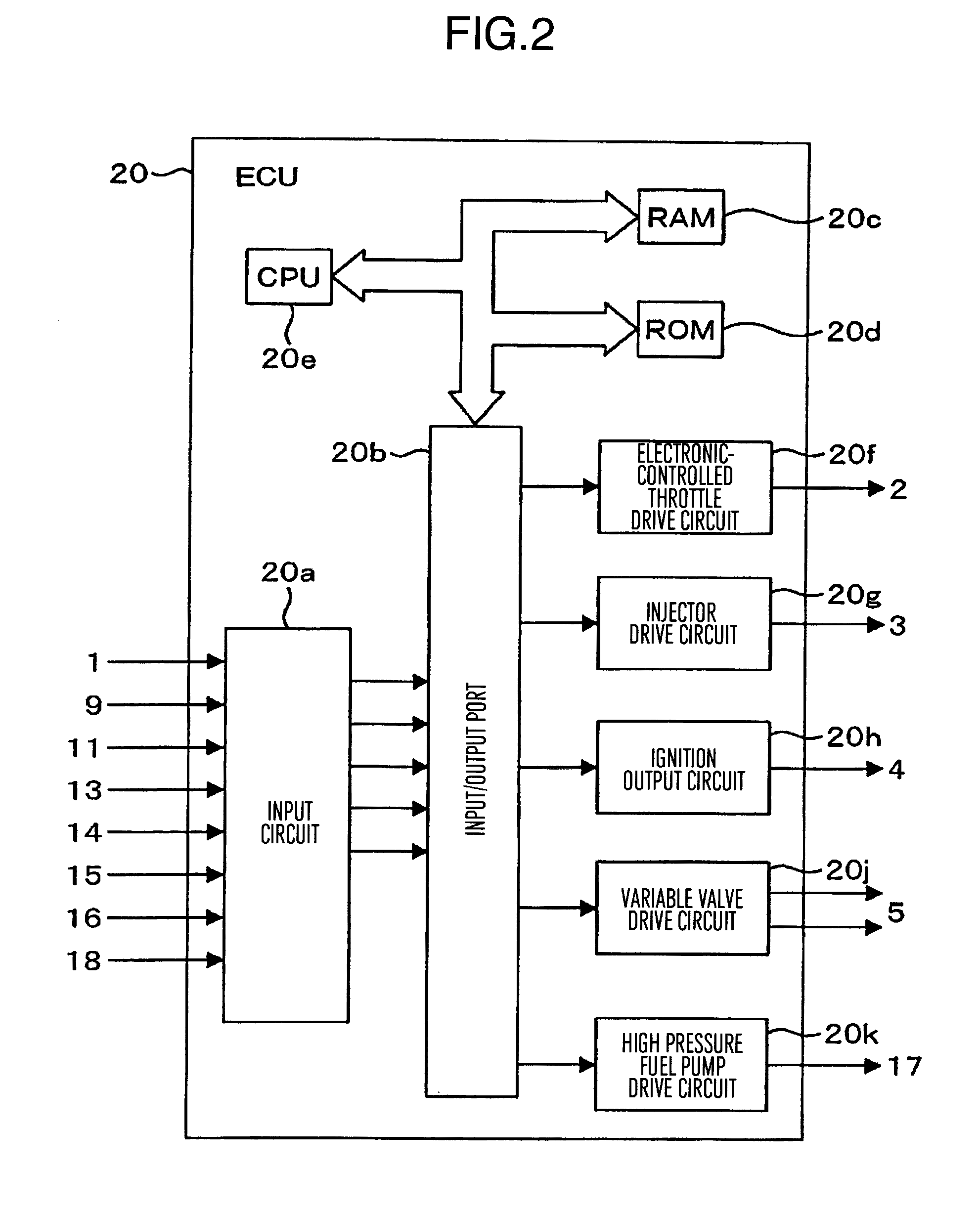
[0097]The configuration of the control apparatus of the direct injection gasoline engine according to the present embodiment is the same as that shown in FIG. 2.

[0098]The characteristics of the variable valve in the control apparatus of the direct injection gasoline engine according to the present embodiment are the same as those shown in FIG. 3.

[0099]Next, contents of the control of the variable valve (the exhaust valve) and the air-fuel ratio (the fuel injection amount) in the control apparatus of the direct injection gasoline engine according to the present embodiment will be described with...


PUM


Abstract

In a direct injection gasoline engine, at acceleration operation, an amount of internal EGR is increased by advancing exhaust valve closing timing, and also fuel injection pressure is increased. In this case, range of increase in fuel injection pressure is determined on the basis of the exhaust valve closing timing at present.

Description

BACKGROUND OF THE INVENTION[0001]The present invention relates to a control apparatus of a gasoline engine, and more particularly to a control apparatus suitable for reducing an amount of emission of so-called particulate matters (PM) in a direct injection gasoline engine.[0002]The direct injection gasoline engine has a problem that it has a larger amount of PM emission than an intake port injection type gasoline engine. The causes of this problem are fuel adhesion to a cylinder and a piston due to direct injection of fuel into the cylinder, and existence of local fuel rich regions caused by insufficient mixing of fuel and air. Therefore, as measure for reducing the amount of PM emission in the direct injection gasoline engine, it is effective to reduce an amount of fuel adhesion and to promote mixing of fuel and air.[0003]As technique to suppress the amount of PM emission in the direct injection gasoline engine, technique is known in which hot exhaust gas is made to exist in the co...

Claims


Application Information

Patent Timeline
IPC IPC(8): F02B3/00B60L50/16
CPCF02D41/3818F02D41/006F02D41/10Y02T10/47Y02T10/18Y02T10/123F02D13/0219F02D2250/31F02M25/0752F02B2075/125F02D41/3836F02D13/0265F02M26/01Y02T10/12Y02T10/40
Inventor KUMANO, KENGOSUKEGAWA, YOSHIHIROKIHARA, YUSUKEOKAMOTO, TAKASHI
Owner HITACHI AUTOMOTIVE SYST LTD
Why Eureka
Try Eureka