Ion detector for mass spectrometry, method for detecting ion, and method for manufacturing ion detector

a technology of mass spectrometry and ion detector, which is applied in the direction of instruments, particle separator tube details, separation processes, etc., can solve the problem that s/n has not become of sufficient performance, and achieve the effect of improving the effect of stray light reduction

Active Publication Date: 2012-04-26
CANON ANELVA CORP
View PDF4 Cites 3 Cited by
  • Summary
  • Abstract
  • Description
  • Claims
  • Application Information

AI Technical Summary

Benefits of technology

[0029]According to the invention, a lead-in electrode for pulling in an ion to a first-stage electrode side of a secondary electron multiplier is provided, and an area of the lead-in electrode and/or a potential difference between an electrode (for example, deflection board etc.) neighboring the lead-in electrode but being separated from electrodes of the secondary electron multiplier (for example, elec

Problems solved by technology

Consequently, the S/N has not beco

Method used


Image

  • Ion detector for mass spectrometry, method for detecting ion, and method for manufacturing ion detector
  • Ion detector for mass spectrometry, method for detecting ion, and method for manufacturing ion detector
  • Ion detector for mass spectrometry, method for detecting ion, and method for manufacturing ion detector

Examples


first embodiment

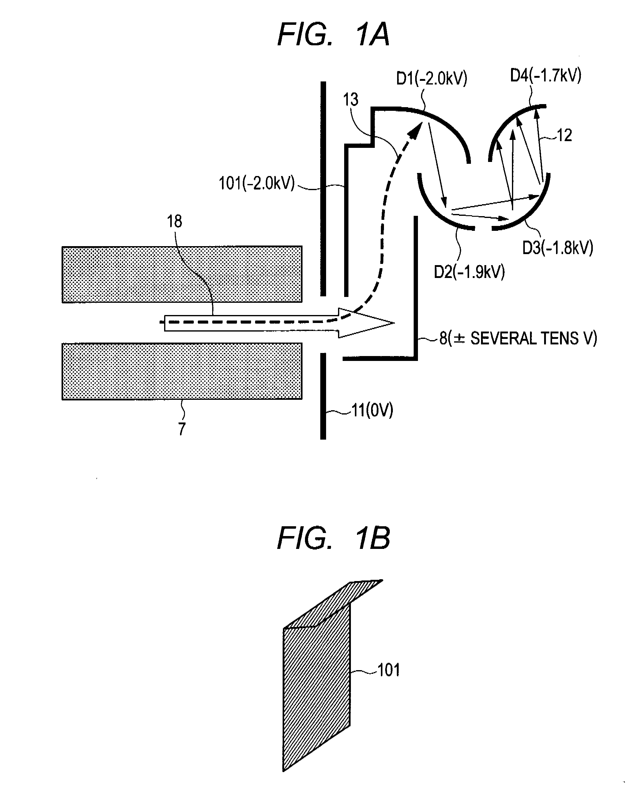
[0117]FIG. 1A is a schematic view showing a part of the mass spectrometer according to the embodiment of the invention, and is a schematic view for explaining an ion analysis unit. FIG. 1B is a perspective view of the lead-in electrode of the ion analysis unit in FIG. 1A.

[0118]In the embodiment, the secondary electron multiplier has 20 stage electrodes, but, in FIG. 1A, electrodes up to the fourth stage (four electrodes) are shown. In the embodiment, the electrode D1 provided at the first-stage of the secondary electron multiplier and the electrode D2 provided at the second stage are provided facing each other, and a kth electrode Dk (k is an integer of 2 or more) is provided, facing a (k−1)th electrode Dk−1 being the electrode of the previous stage thereof and a (k+1)th electrode Dk+1 being the electrode of the rear stage thereof.

[0119]That is, each of electrodes D1 to D20 is provided so that an electron generated by the collision of an ion against the electrode D1 provided for the...

second embodiment

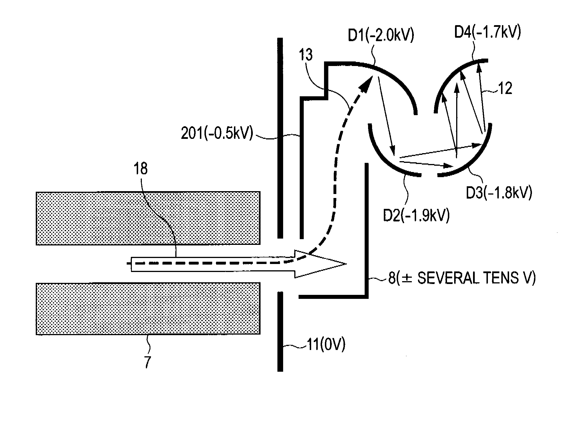
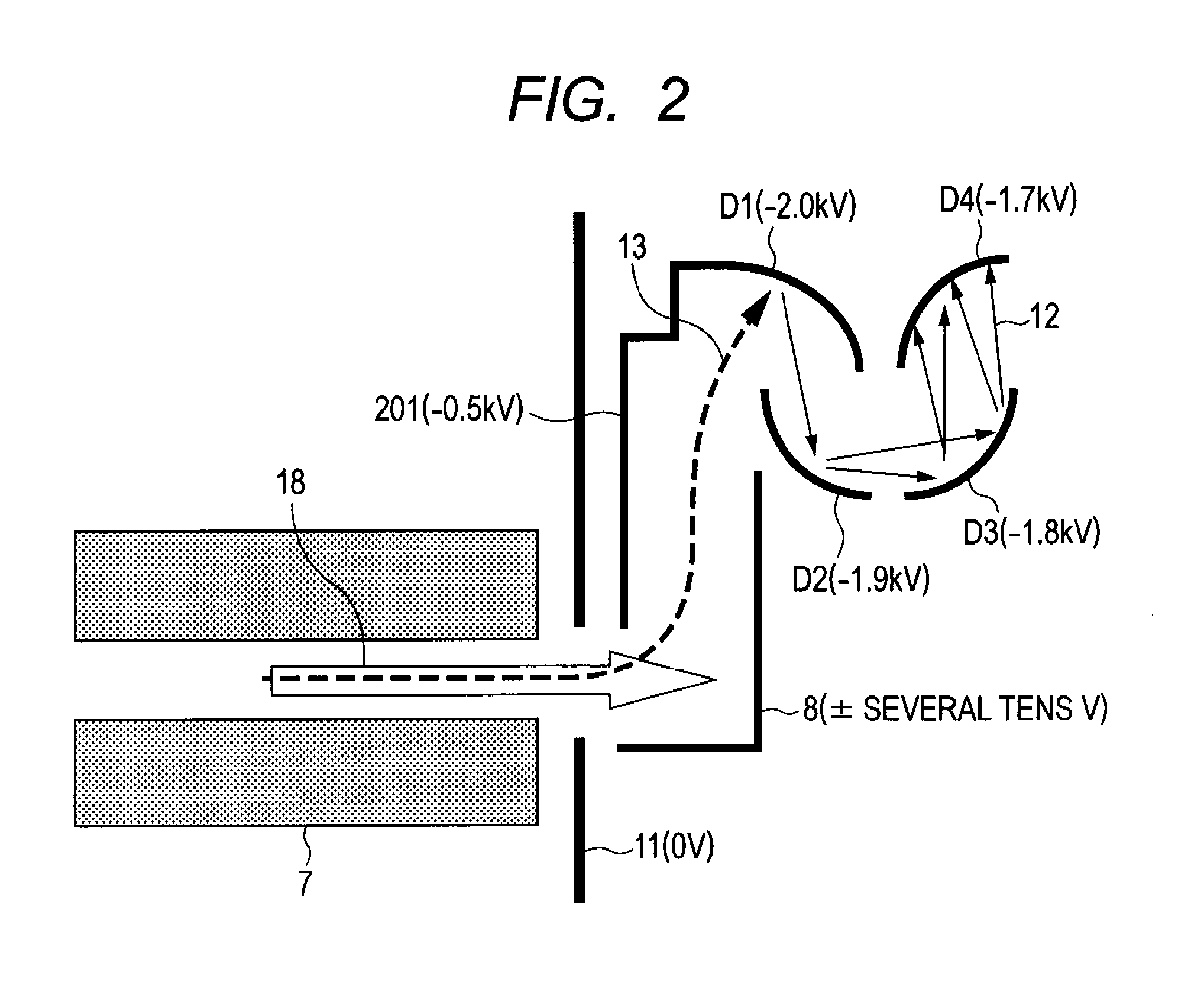
[0130]FIG. 2 is a schematic view showing a part of the mass spectrometer according to the embodiment, and a schematic view for explaining an ion analysis unit. The embodiment is different from the examination example of the invention only in that the applied potential to a lead-in electrode 201 is −500 V, and the others are the same.

[0131]In the embodiment, the ion 13 ejected from the mass aperture board 11 is pulled in toward the SEM 9 direction mainly by the electric field by the lead-in electrode 201, wherein the applied potential to the lead-in electrode for pulling in the ion is changed from −2 kV in the examination example of the invention to −500 V. Accordingly, the ion pull-in effect is reduced a little, but, when compared with the second and third conventional examples, the detection efficiency for original ions to be detected is considerably improved. And, although the amount of high-energy electrons generated on the lead-in electrode 201 is the same as that in the examina...

third embodiment

[0138]FIG. 3A is a drawing showing a part of the mass spectrometer according to the embodiment, and is a schematic view for explaining an ion analyzer. FIG. 3B is a perspective view showing the lead-in electrode and the deflection board of the ion analyzer shown in FIG. 3A. The embodiment is different from the examination example of the invention only in that the deflection board 8 is divided into two and, to a second deflection board 302 facing the lead-in electrode 20 of the deflection boards divided into two, a potential of −1.5 kV is applied, and the others are identical.

[0139]As shown in FIGS. 3A and 3B, the embodiment uses two deflection boards 301 and 302. And, to the deflection board 301 provided on the previous stage side in the traveling direction of the ion 13, a potential of ±several tens V is applied, and, to the deflection board 302 provided on the rear stage side, a potential of −1.5 kV is applied.

[0140]Most of high-energy electrons generating on the lead-in electrode...


PUM


Abstract

The present disclosure provides an ion detector for improving the effect of electric field for pulling in an ion to be detected to a first-stage electrode of a secondary electron multiplier (SEM), and improving the effect of a stray light reduction. In one example embodiment, an ion detector includes a SEM, and a lead-in electrode for pulling in an ion to a first-stage electrode side of the SEM. At least one of the area of the lead-in electrode and a potential difference between the lead-in electrode and neighboring electrodes of the lead-in electrode, the neighboring electrode being an electrode not of the SEM, is set so that the light amount of internal-stray light generated inside the detector entering the first-stage electrode is not more than that of external-stray light generated outside the detector entering the first-stage electrode, when an ion is introduced into the detector.

Description

CROSS-REFERENCES TO RELATED APPLICATIONS[0001]This application is a continuation application of International Application No. PCT / JP2009 / 058462, filed Apr. 30, 2009. The contents of the aforementioned applications are incorporated herein by reference in their entities.TECHNICAL FIELD[0002]The present invention relates to an ion detector and a method for detecting an ion detecting a mass-selected ion with an extremely high S / N (a signal / noise ratio) in mass spectrometer, and a method for manufacturing an ion detector.BACKGROUND ART[0003]The mass spectrometer is an analyzer capable of measuring the abundance for every mass number of sample components, and has such large characteristic as extremely high sensitivity (low detection limit) as compared with other analyzers. One of elements realizing this is a unit (an ion detection unit) detecting a mass-selected ion, which includes a secondary electron multiplier (SEM), a deflection board, a collector etc. The SEM has electrodes of around...

Claims


Application Information

Patent Timeline
IPC IPC(8): H01J49/06H01J43/06
CPCH01J49/00H01J43/10
Inventor NAKAMURA, MEGUMISHIOKAWA, YOSHIROPENG, QIANG
Owner CANON ANELVA CORP
Why Eureka
Try Eureka