
Elastic wave device and method for manufacturing the same

a technology of elastic wave and manufacturing method, which is applied in the direction of generator/motor, piezoelectric/electrostrictive transducer, transducer type, etc., can solve the problems of not generating damage caused by elastic layer, and achieve the effect of reducing the design degree of freedom, reducing the deformation of elastic wave device, and reducing the size of the devi

Active Publication Date: 2012-04-26
MURATA MFG CO LTD
View PDF2 Cites 17 Cited by
  • Summary
  • Abstract
  • Description
  • Claims
  • Application Information

AI Technical Summary

Benefits of technology

[0009]Therefore, preferred embodiments of the present invention provide an elastic wave device which prevents various troubles generated during bonding as described above and which structurally causes no degradation in performance and a method for manufacturing the elastic wave device described above.

Problems solved by technology

In addition, since the inorganic layer is provided between the elastic layer and the piezoelectric thin film, damping caused by the elastic layer is not generated.

Method used


Image

  • Elastic wave device and method for manufacturing the same
  • Elastic wave device and method for manufacturing the same
  • Elastic wave device and method for manufacturing the same

Examples


Embodiment Construction

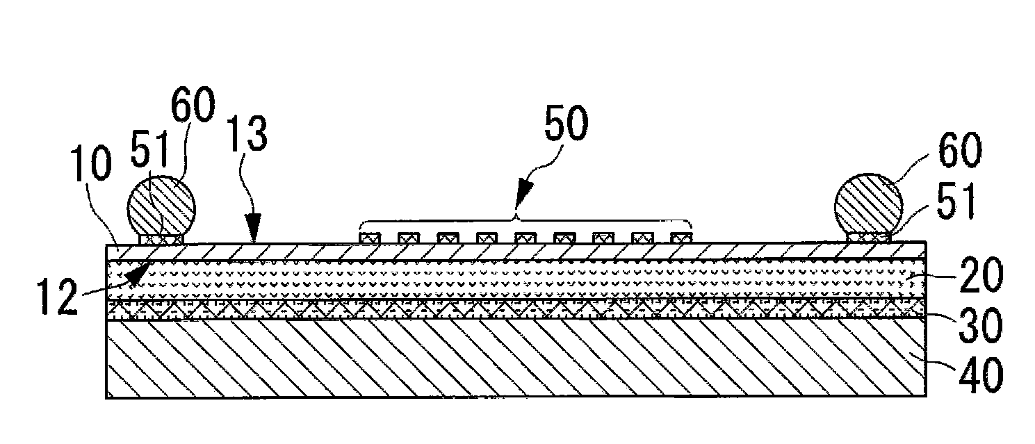
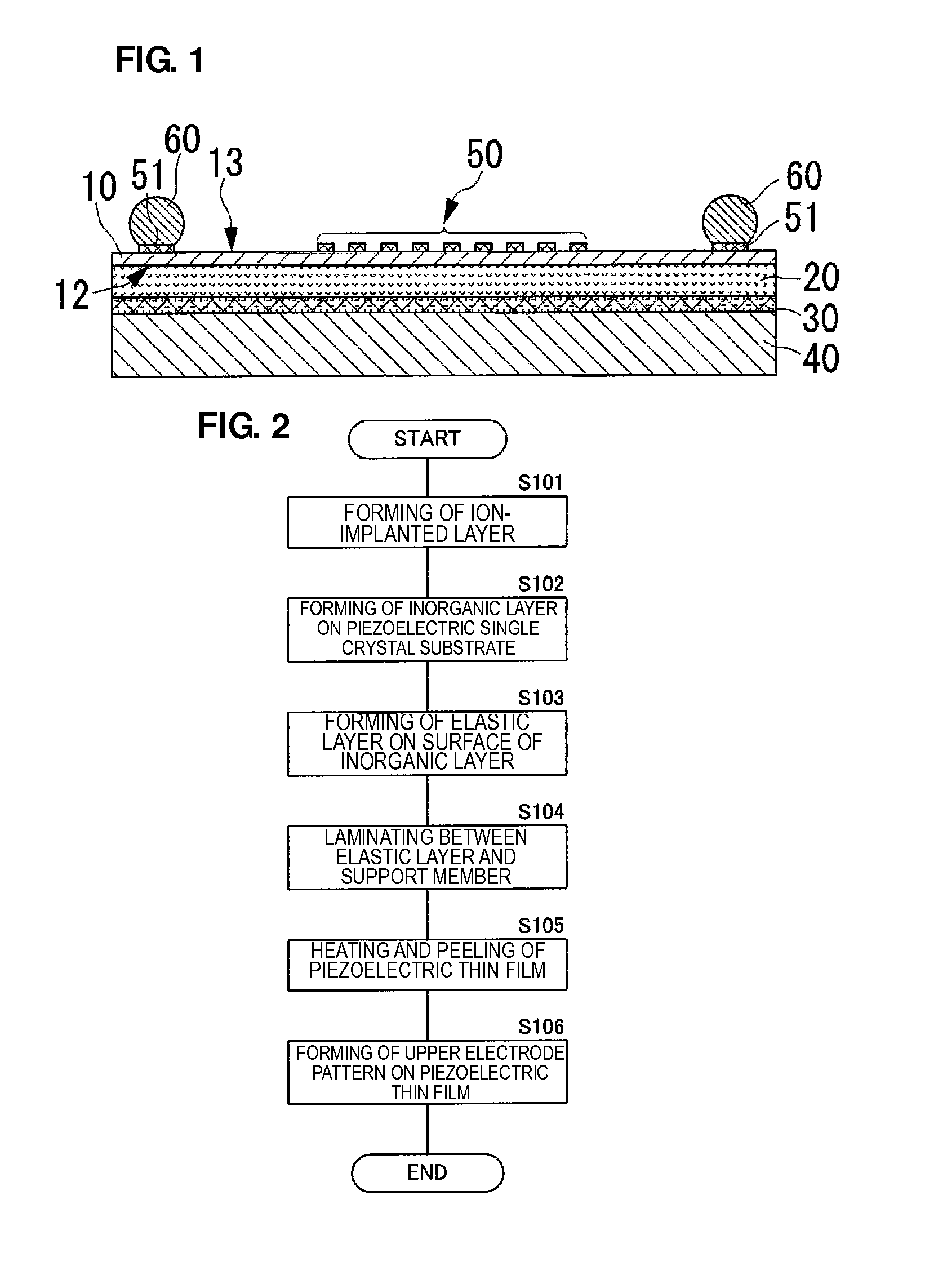
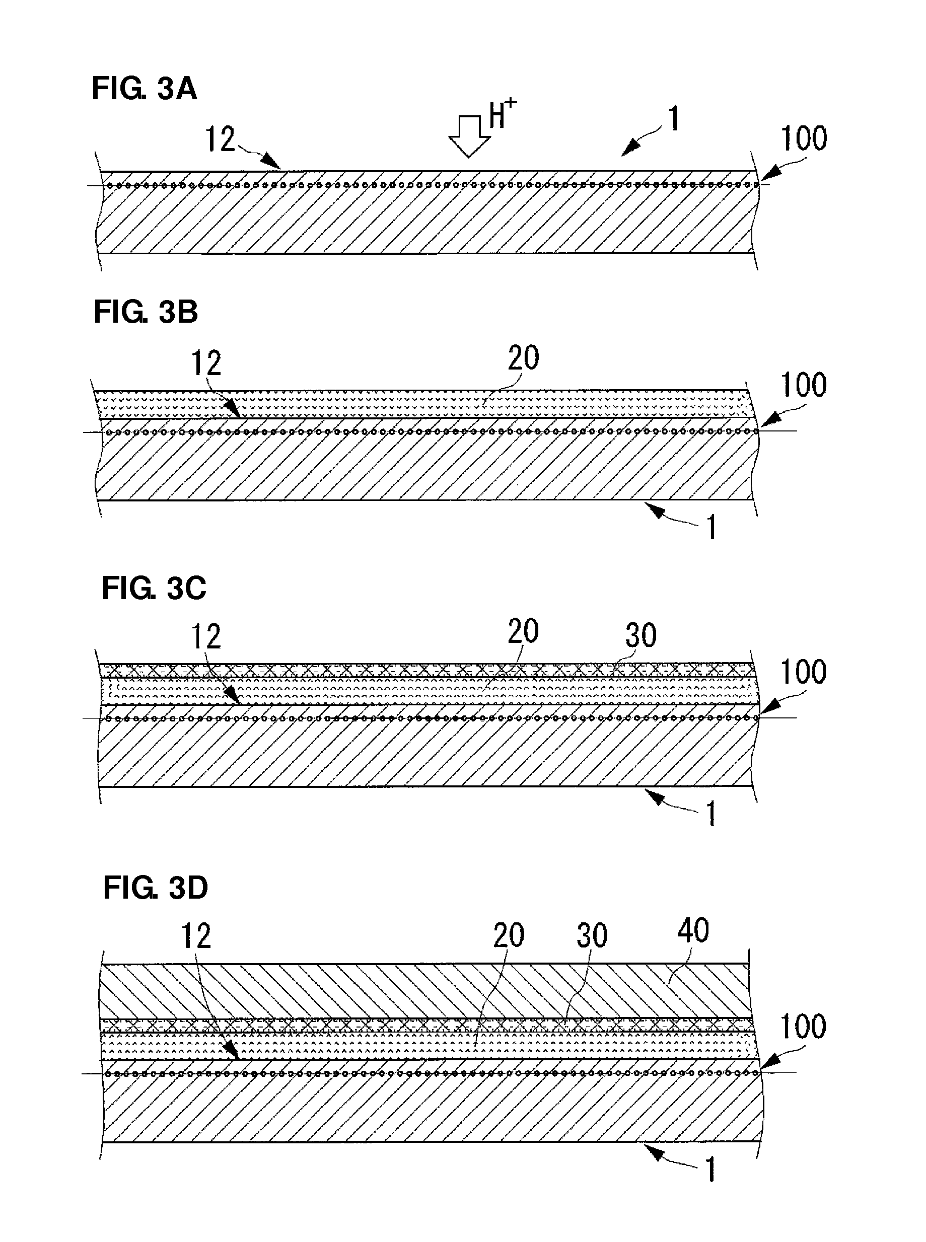
[0039]An elastic wave device according to a first preferred embodiment of the present invention and a method for manufacturing the elastic wave device will be described with reference to the drawings. In addition, in the present preferred embodiment, a surface acoustic wave device will be described by way of example. FIG. 1 is a side cross-sectional view showing the structure of the elastic wave device according to the present preferred embodiment. An elastic wave device includes a piezoelectric thin film 10 made of a piezoelectric single crystal, such as LT, preferably having a thickness of approximately 1 μm, for example. In addition, for the piezoelectric thin film 10, besides LT, for example, a material, such as LN, LBO (Li2B4O7), langasite (La3Ga5SiO14), KN (KNbO3), or KLN (K3Li2Nb5O15), which has piezoelectricity and which can be processed by a smart cut method, is preferably used.

[0040]An IDT electrode 50, bump pads 51, and a circuit pattern (not shown) which electrically con...


PUM

PropertyMeasurementUnit
Pressureaaaaaaaaaa
Electrical conductivityaaaaaaaaaa
Elasticityaaaaaaaaaa

Abstract

An elastic wave device includes a piezoelectric thin film formed from a piezoelectric single crystal substrate by peeling, an inorganic layer formed on a rear surface of the piezoelectric thin film, an elastic layer disposed on a surface of the inorganic layer opposite to the piezoelectric thin film, and a support member adhered to a surface of the elastic layer opposite to the inorganic layer. The elastic layer reduces stress generated when the piezoelectric thin film provided with the inorganic layer and the support member are adhered to each other and has a predetermined elastic modulus. The inorganic layer is formed of a material having a higher elastic modulus than that of the elastic layer and prevents damping generated when the elastic layer is provided.

Description

BACKGROUND OF THE INVENTION[0001]1. Field of the Invention[0002]The present invention relates to an elastic wave device including a thin film of a piezoelectric single crystal and a method for manufacturing the elastic wave device.[0003]2. Description of the Related Art[0004]In recent years, many piezoelectric devices each including a thin film of a piezoelectric single crystal have been developed. In the piezoelectric device including a piezoelectric thin film as described above, a support member supporting the piezoelectric thin film is necessary in practical use. As disclosed in Japanese Unexamined Patent Application Publication No. 2007-228319 and Japanese Unexamined Patent Application Publication No. 2003-17967, the support member as described above is provided on one primary surface of the piezoelectric thin film.[0005]In addition, as one of methods for forming a composite piezoelectric substrate formed of the piezoelectric thin film and the support member as described above, ...

Claims


Application Information

Patent Timeline
IPC IPC(8): H01L41/047B32B38/10
CPCY10T29/42H03H3/08
Inventor IWAMOTO, TAKASHIKANDO, HAJIME
Owner MURATA MFG CO LTD
Learn More