High Efficiency Variable Voltage Supply

a variable voltage and high efficiency technology, applied in the direction of electric variable regulation, process and machine control, instruments, etc., can solve the problems of high final stage efficiency, poor efficiency, implementation of such dynamic supply adjustment techniques, etc., and achieve the effect of minimising the peak amplitude of error level and minimising the slew rate of error level

Inactive Publication Date: 2012-04-26
SNAPTRACK
View PDF2 Cites 0 Cited by
  • Summary
  • Abstract
  • Description
  • Claims
  • Application Information

AI Technical Summary

Benefits of technology

[0017]The power supply stage may be adapted to maximise the efficiency of the high efficiency variable voltage supply, whilst maintaining a low peak-to-average ratio for the error level. The power supply stage may be adapted to maximise the efficiency of the high efficiency variable voltage supply, whilst maintaining a low slew rate for the error level. A ratio of peak error signal to peak output signal is preferably maintained at less than 0.5 A ratio for peak error signal slew rate to peak output signal slew rate is preferably less than 1.5.
[0028]The correction element of the adjusting means may be optimised to provide accurate error tracking. The correction element of the adjusting means may be further optimised to deliver high peak to mean output power with good efficiency. The correction element of the adjusting means may be a linear Class-G amplifier having multiple power supplies. The correction element of the adjusting means may be a linear Class-H amplifier having multiple power supplies.
[0037]The efficiency of the variable voltage supply may be maximised, whilst jointly minimising the peak-to-average ratio of the error level and the slew rate of the error level. A ratio of peak error signal to peak output signal may be maintained at less than 0.7, and a ratio for peak error signal slew rate to peak output signal slew rate may be maintained at less than 1.5.
[0050]The method may further comprise minimising the peak amplitude of the error level. The method may further comprise maintaining a ratio of peak error level to peak output level of less than 1. The ratio of the peak error level to peak output level may be maintained at less than 0.7.
[0051]The method may further comprise minimising the slew rate of the error level. The ratio of the peak slew rate of error level to the peak slew rate of the output level may be maintained as less than 1.5.

Problems solved by technology

This generally results in poor efficiency.
This results in high final stage efficiencies.
At least three problems exist in implementing such dynamic supply adjustment techniques.
Secondly, any noise or distortion in the supply to the amplifier will be modulated up to the carrier frequency resulting in unacceptable out-of-band spectral emissions.
When applied to high power broadband systems such as multi-carrier WCDMA (wideband code division multiple access), prior art attempts to address this problem using either Class-S modulators (pulse width modulation) or Class-G modulators (switched supply) exhibit unacceptable performance due to insufficient tracking bandwidth, excessive switching losses, or unacceptable distortion characteristics.

Method used


Image

  • High Efficiency Variable Voltage Supply
  • High Efficiency Variable Voltage Supply
  • High Efficiency Variable Voltage Supply

Examples


Embodiment Construction

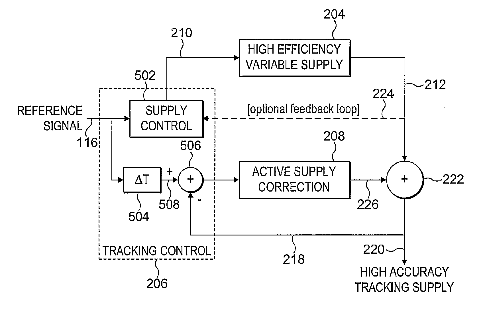
[0071]The invention is described herein by way of particular examples and specifically with reference to a preferred embodiment or embodiments. It will be understood by one skilled in the art that the invention is not limited to the details of the specific embodiments given herein. In particular the invention is described herein by way of reference to a supply architecture for supplying a radio frequency (RF) amplification stage. However more generally the invention may apply to any arrangement where it is necessary to provide a variable voltage level tracking a reference level.

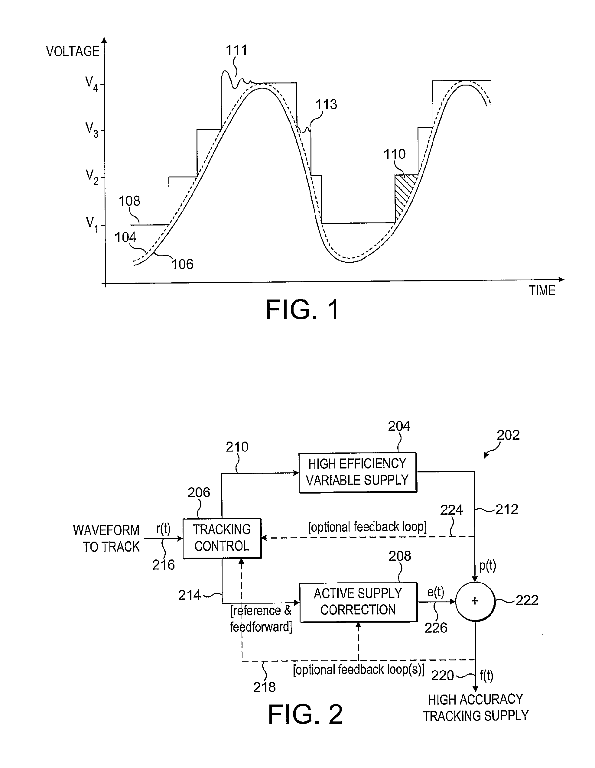
[0072]Reference is first made to FIG. 1, which illustrates the concept of an envelope tracking supply voltage, and the problems associated therewith. The problem is described in relation to a variable voltage supply for a radio frequency (RF) amplifier, the voltage supply being varied to track the RF input signal to be amplified. By way of example, it is assumed that the variable voltage supply is provided by...


PUM


Abstract

There is disclosed a power supply stage, comprising: generating means for generating a power supply voltage from a high efficiency variable voltage supply in dependence on a reference signal; adjusting means for receiving the generated power supply voltage, and adapted to provide an adjusted selected power supply voltage tracking the reference signal in dependence thereon.

Description

CROSS REFERENCE TO RELATED APPLICATIONS[0001]This application claims priority to U.S. patent application Ser. No. 11 / 574,218, with a U.S. filing date of Aug. 2, 2007, and is incorporated herein by reference. U.S. application Ser. No. 11 / 574,218 is a 371 filing of PCT / GB2005 / 003318, filed on Aug. 25, 2005 which in turn claims priority to British Application Number 0418991.6, filed on Aug. 25, 2004.FIELD OF THE INVENTION[0002]The present invention relates to control of a supply voltage level, in an arrangement in which the supply voltage is variable to track a reference level, which reference level may represent a signal to be amplified.BACKGROUND TO THE INVENTION[0003]Modern communications systems often employ linear modulation schemes that exhibit high peak to average power ratios to achieve high capacity. Signals subjected to such modulation have a wide dynamic range, infrequently achieve peak levels, and frequently operate below peak levels. To provide linear amplification for sig...

Claims


Application Information

Patent Timeline
Patent Type & Authority Applications(United States)
IPC IPC(8): G05F5/00H03F1/02
CPCH03F1/0211H02M5/02H03F2200/504G05F5/00H03F1/0233H03F3/19H03F2200/102H03F2200/204H03F2200/451
Inventor WILSON, MARTIN PAULFLINT, SHANE
Owner SNAPTRACK
Why Eureka
Try Eureka