
Image forming apparatus

a technology of image forming apparatus and forming apparatus, which is applied in the direction of electrographic process apparatus, instruments, optics, etc., can solve the problems of improper separation, low rigidity, and unstable transfer property, and achieve the effect of suppressing a lowering of separation property and enhanced electrostatic attraction property

Inactive Publication Date: 2012-04-26
CANON KK
View PDF1 Cites 5 Cited by
  • Summary
  • Abstract
  • Description
  • Claims
  • Application Information

AI Technical Summary

Benefits of technology

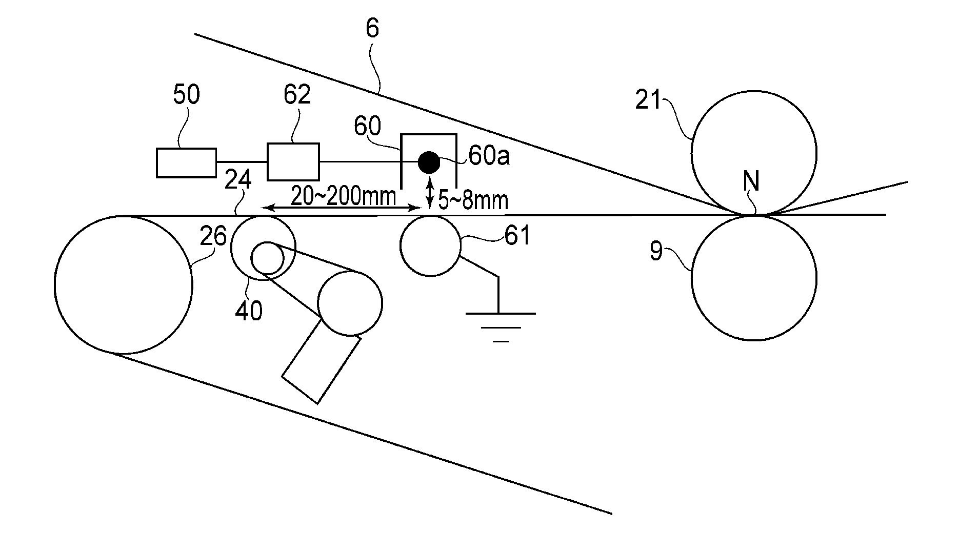
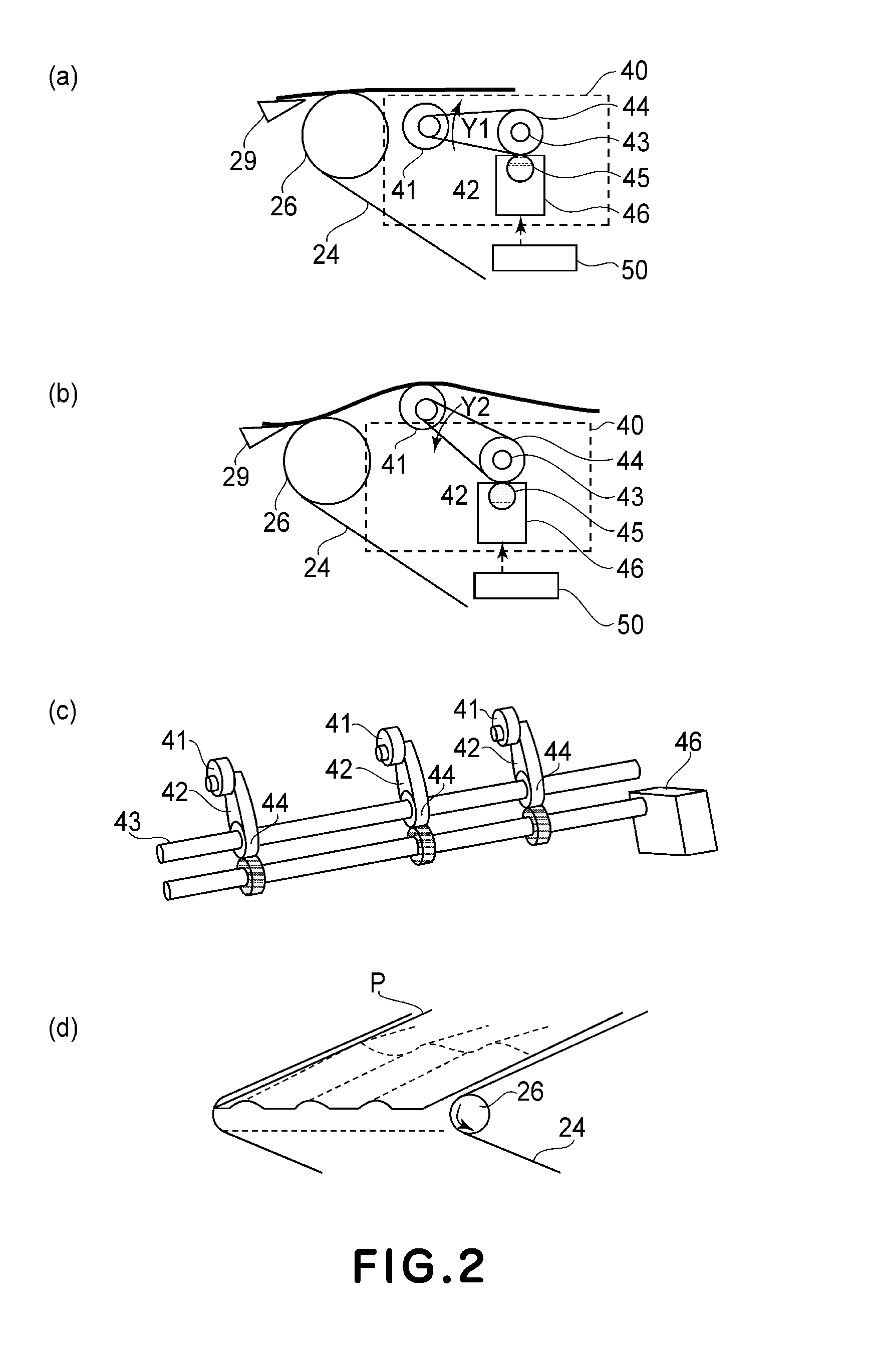
[0010]A principal object of the present invention is to enhance an electrostatic attraction property between a recording material and a transfer belt at a push-up deformation portion to suppress a lowering in separation property even when a transfer current is small in a constitution in which the recording material is deformed by locally pushing up the transfer belt by a push-up means.
[0011]A specific object of the present invention is to provide an image forming apparatus capable of suppressing the lowering in separation property even when the transfer current is small by enhancing the electrostatic attraction property between the recording material and the transfer belt at the push-up deformation portion.

Problems solved by technology

However, with respect to such thin paper or the like has the low rigidity and therefore a recording material conveying method capable of further enhancing stability is required.
However, in a technique in which the recording material is separated by curvature from the transfer belt by using a separation roller, in the case of the low-rigidity recording material, a leading end of the recording material is still adhered to the transfer belt at a separation portion where the separation roller is provided, so that improper separation occurs.
As a result, a transfer property is not stabilized by the influence of a resistance non-uniformity due to local abrasion of the transfer belt.
In an apparatus in which the recording material is nip-conveyed by the transfer belt and is separated by curvature from the transfer belt by using the separation roller, when the resilience of the recording material is weak (when the rigidity of the recording material is low), separation becomes unstable.
In the case where the transfer current is small, respective charge amounts become small, so that an attraction force between the recording material and the transfer belt is weaken.
As a result, deformation of the recording material becomes insufficient and thus the resilience of the recording material becomes weak, so that a problem that a separating property by the separation roller is lowered occurs.

Method used


Image

  • Image forming apparatus
  • Image forming apparatus
  • Image forming apparatus

Examples


embodiment 1

(Image Forming Apparatus)

[0034]The image forming apparatus according to the present invention will be described.

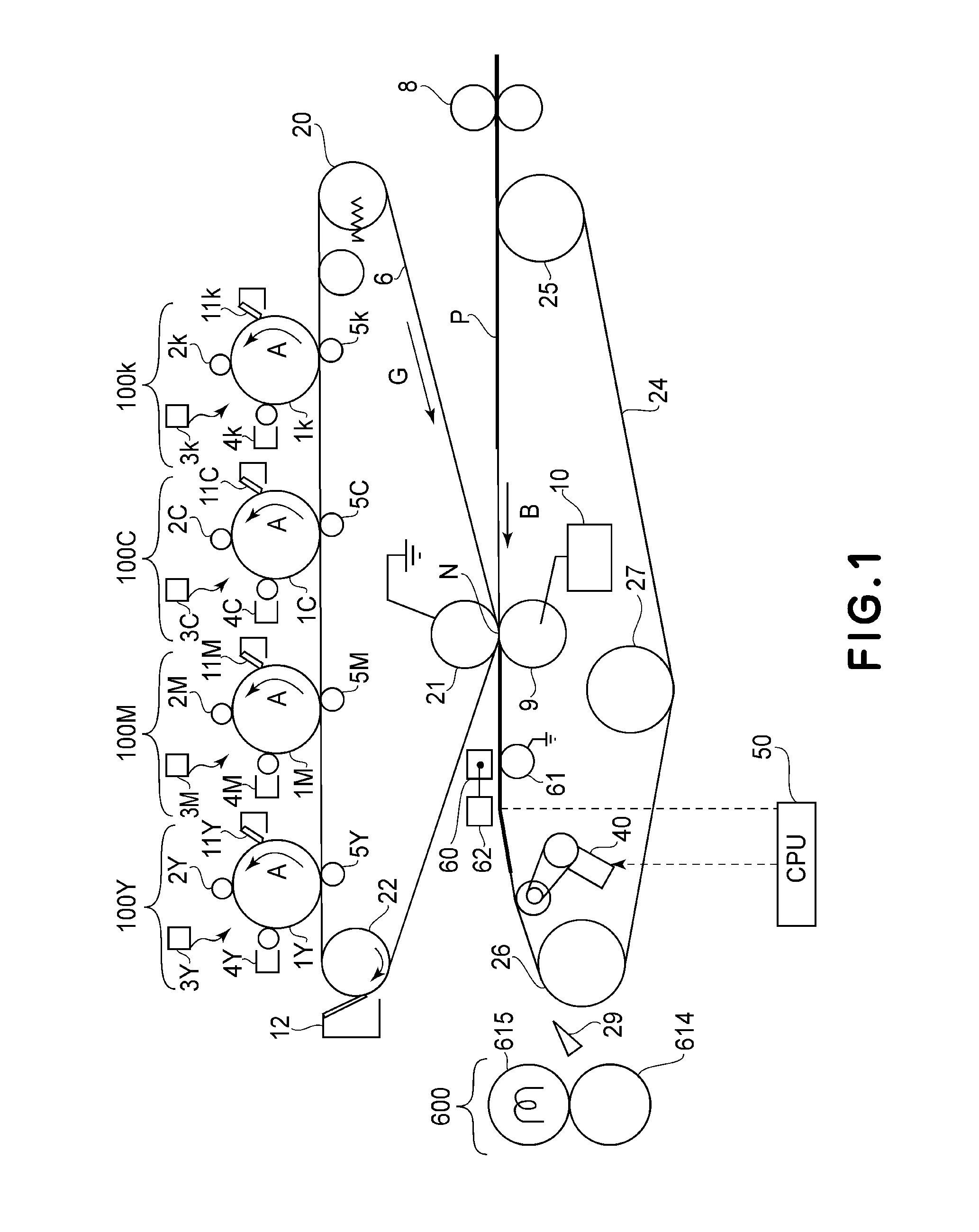
[0035]First, a constitution and operation of the image forming apparatus will be described with reference to FIG. 1. The image forming apparatus shown in FIG. 1 is a color image forming apparatus using an electrophotographic process. FIG. 1 is a sectional view of the image forming apparatus of a so-called intermediary transfer tandem type in which four color image forming portions are juxtaposed on an intermediary transfer belt.

[0036]First, an image forming portion (image forming unit) 100 will be described. In this embodiment, well-known image forming units 100Y, 100M, 100C and 100k are provided. Next, each of the image forming portions will be described.

[0037]Photosensitive drums 1Y, 1M, 1C and 1K as an image bearing member are rotationally driven in an arrow A direction.

[0038]Charging devices 2Y, 2M, 2C and 2k are used for charging the respective photosensitive drums. E...

embodiment 2

[0092]In the constitution in Embodiment 1, when the auxiliary separation device is operated on the basis of the type of the recording material, the preset voltage is applied to the pre-separation charger. On the other hand, this embodiment is characterized in that the voltage applied to the pre-separation charger is changed depending on the secondary transfer voltage.

[0093]Generally, the secondary transfer current value is fluctuated depending on various conditions (a drying state of paper, environment, a maximum charge density of the toner to be transferred, and the like) and therefore the amount of the charge of the recording material after passing through the secondary transfer portion fluctuates. When the recording material charge amount is decreased, the attracting force of the recording material to the transfer belt is weakened and thus the recording material is liable to be separated from the transfer belt during the wavy shape formation by the auxiliary separation device, so...

embodiment 3

[0104]In Embodiment 3, flowability of the developer in the developing device is detected and the value of the bias applied to the pre-separation charger is determined depending on the detected flowability of the developer, so that the amount of electric charge provided to the recording material is changed.

[0105]A degree of the image defect due to the electric discharge during the separation between the recording material P and the transfer belt 24 depends on the developer flowability. That is, when the flowability is high, the unfixed toner on the recording material is liable to move in an in-plane direction. Further, the electric charge provided to the recording material by the electric discharge has the same polarity to the normal charge polarity of the toner and thus the toner is liable to move in the in-plane direction by the Coulomb force acting between the toner and the electric charge provided to the recording material, so that the image is liable to disturbed.

[0106]Generally...


PUM


Abstract

An image forming apparatus includes an image bearing member; a stretched rotatable belt member; a transfer member for forming a toner image onto a recording material carried on the belt member; a separation roller, for stretching the belt member; a push-up device for pushing up a belt surface of the belt member; a pre-separation charging device, for electrically charging the recording material with a voltage of an opposite polarity to a normal charge polarity of a toner; and an execution portion for executing an operation in which the recording material charged by the voltage to the pre-separation charging means is separated from the belt member by pushing up the belt member by the push-up device.

Description

FIELD OF THE INVENTION AND RELATED ART[0001]The present invention relates to a transfer technique, in which a toner image formed on an image bearing member is transferred onto a recording material by using an electrophotographic apparatus such as a copying machine or a laser beam printer. Further, the present invention relates to a separation technique for separating the recording material from a transfer belt for nip-conveying of the recording material.[0002]In recent years, an image forming apparatus using an electrophotography, such as the copying machine or the laser beam printer has been required to meet various recording materials. As an object thereof, the image forming apparatus has been required to meet the recording material which has low rigidity such as thinner paper. However, with respect to such thin paper or the like has the low rigidity and therefore a recording material conveying method capable of further enhancing stability is required.[0003]Therefore, the recordin...

Claims


Application Information

Patent Timeline
Patent Type & Authority Applications(United States)
IPC IPC(8): G03G15/16
CPCG03G2215/0129G03G15/1605G03G15/6532
Inventor IDEGUCHI, TAKURO
Owner CANON KK
Learn More