Semi-rigid compression splint for application of three-dimensional force

a compression splint and three-dimensional force technology, applied in the field of compression splints for trauma, can solve the problems of insufficient pre-hospital time and talent for this procedure, the inability to apply force to the soft anterior abdominal/pelvic wall, and the inability to reduce the number of patients, reduce the number of long bone fractures or pelvis, and achieve no deleterious effects on cardio-pulmonary mechanics

Inactive Publication Date: 2012-04-26
THE RES FOUND OF STATE UNIV OF NEW YORK
View PDF4 Cites 10 Cited by
  • Summary
  • Abstract
  • Description
  • Claims
  • Application Information

AI Technical Summary

Benefits of technology

[0011]The semi-rigid compression splint for trauma is a new device that combines the in-field simplicity of use, non-invasiveness and access to the fracture site that is lacking in the conventional fracture treatment technologies. It is an inexpensive, completely non-invasive, rapidly-applied splint that will provide reduction of long bone fractures or pelvic compression and stabilization at the sacro-iliac joint and the pubic symphysis. No specialized training is required to apply the splint, and can be applied during pre-hospital stabilization at an accident scene, for example, by emergency medical technicians (EMT) of an emergency medical services (EMS) or other first responders, such as f

Problems solved by technology

Furthermore, pelvic compression splints of the prior art cause compressive forces to be applied to the soft anterior abdominal/pelvic wall and not to the bony pelvis itself where it is most needed
Despite these advantages, use is severely limited by the need to have an orthopedic surgeon present that can dissect through skin and muscle and properly place a pin in bone.
Obviously, the required time and talent for this procedure is not available in the pre-hospital context, and rarely, if ever, available in a community hospital that functions in the trauma system as a point for

Method used


Image

  • Semi-rigid compression splint for application of three-dimensional force
  • Semi-rigid compression splint for application of three-dimensional force
  • Semi-rigid compression splint for application of three-dimensional force

Examples


Embodiment Construction

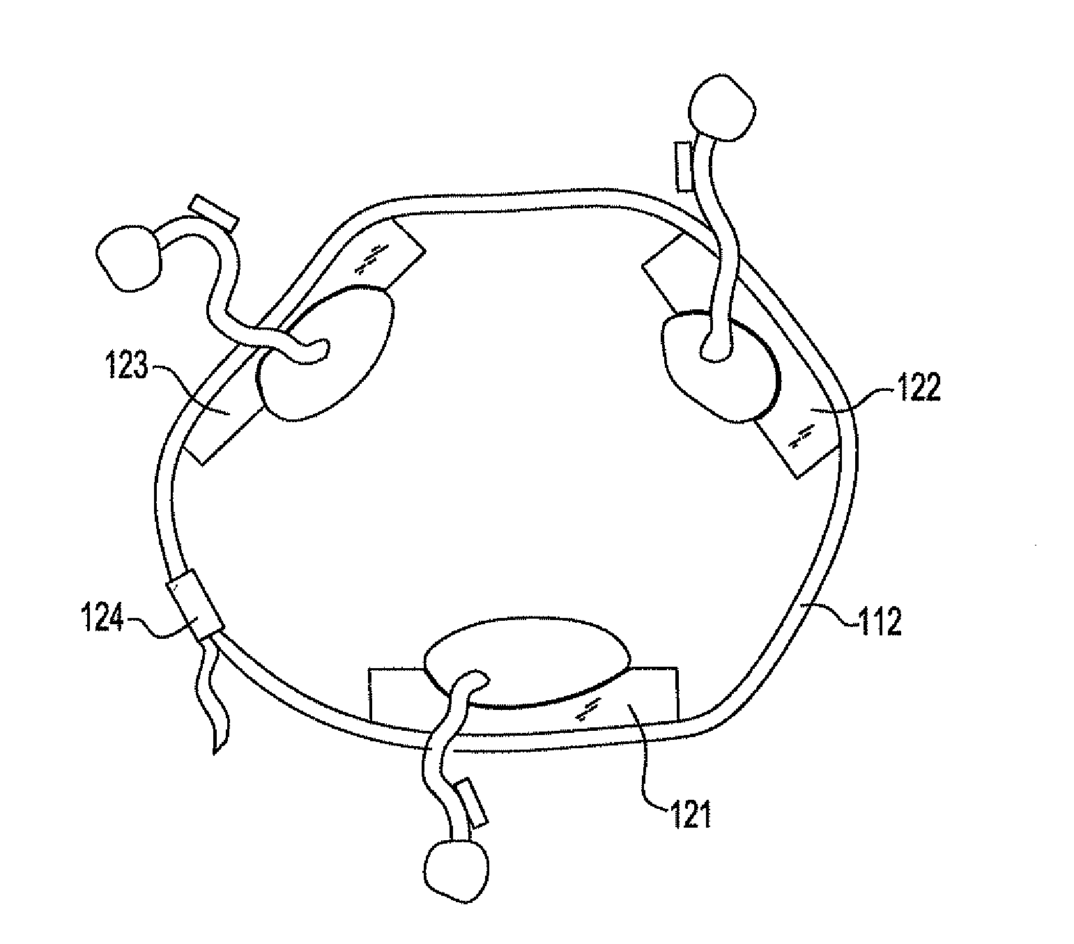
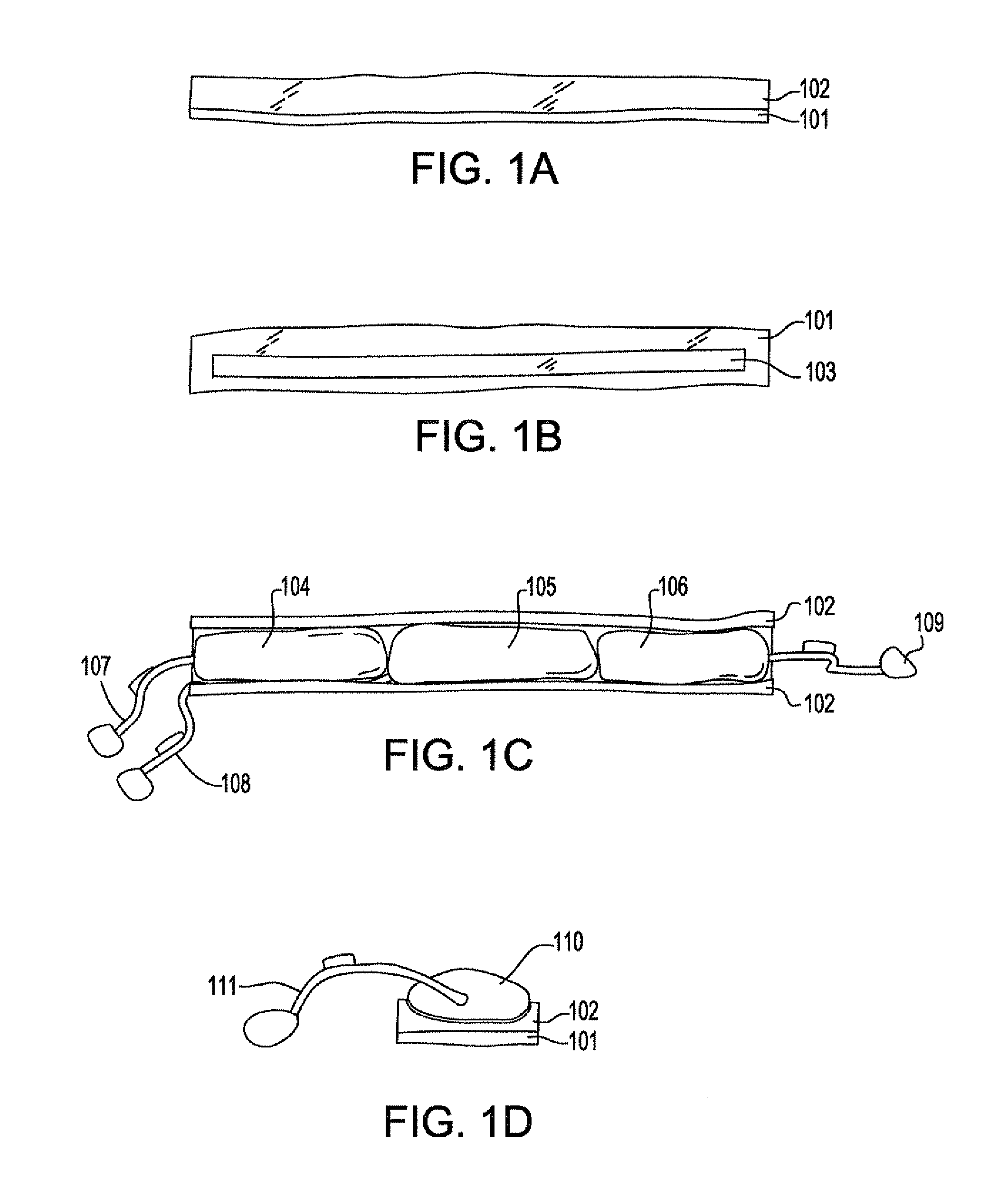
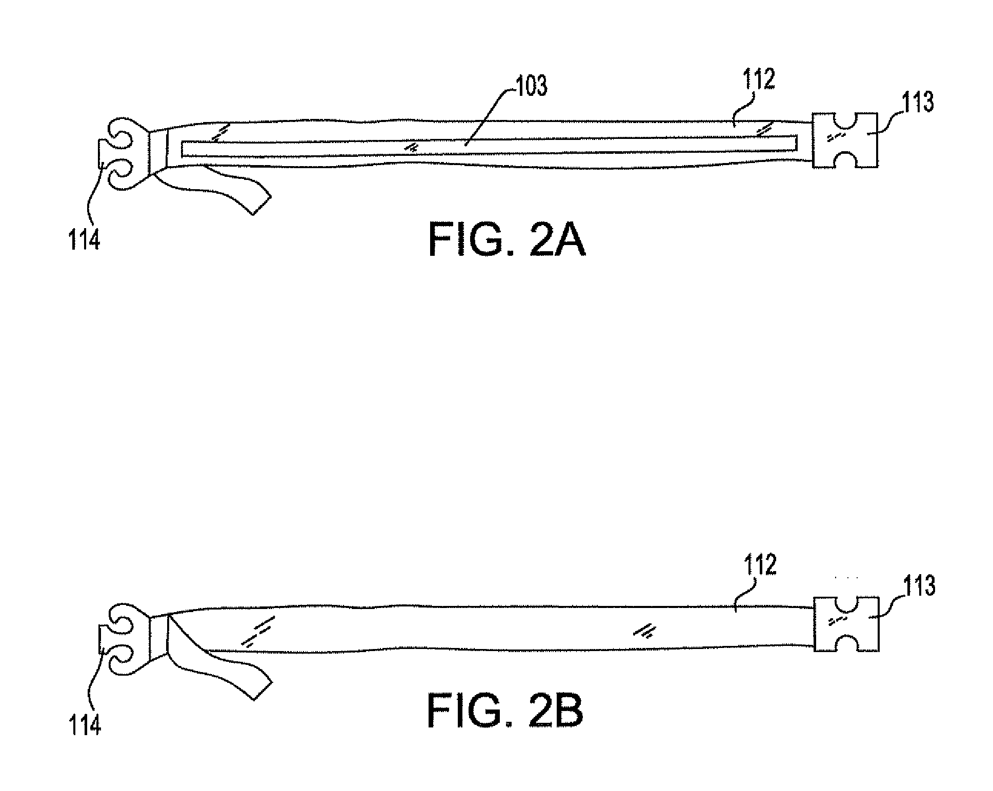
[0022]A semi-rigid compression splint of the present invention will be discussed first in general as applied to a fracture and below with more specificity. The splint, when in an open position is slid posterior to (under) the supine patient's buttocks, when applied to a pelvic fracture, or placed under the patient's head, neck, upper or lower limbs using standard trauma techniques. A plurality of straps and right and left plates form the posterior and lateral aspects of the splint.

[0023]In one embodiment, one end of each of the straps are passed superior to (over) the patient's fracture site and attached to the opposing end of each respective strap. A system of cushions and air bladders are mounted on the internal side of each plate. After the splint is in place on a patient, the air bladders are inflated to compress / stabilize the patient's pelvis. The straps and air bladders may then be further manipulated to optimize the fit and function of the splint.

[0024]The plates are designed...


PUM


Abstract

A compression splint is provided for reduction, compression and stabilization of spinal, pelvic, and long bone fractures. The compression splint includes a plurality of plates selectively disposed at a plurality of positions of a fracture site; a plurality of inflatable cushions, each cushion positioned between respective plates of the plurality of plates and the fracture site; and a support means for supporting the plurality of plates and plurality of cushions compressively against the fracture site in three dimensions, Additionally, the plates of the compression splint can be adjusted, removed or additional plates added to further customize the compressive force applied to the fracture site.

Description

FIELD OF THE INVENTION[0001]The present invention relates generally to compression splints for trauma and, more particularly, to an axial, rotation, semi-rigid compression splint.BACKGROUND OF THE DISCLOSURE[0002]Bone fractures are stabilized with splints until proper diagnosis and treatment are available. Medical personnel align a fractured bone, which is referred to as reduction, and maintain the alignment through various treatments for healing. The following presents approaches to noninvasive reduction of fractures of the pelvis and long bones.[0003]Compression splints of the prior art are typically fabricated from a solid piece of fabric or other material. While these splints have their advantages, in order to ensure that the providers can see and access the area being treated by the splint, such as the spine, limbs, anterior abdomen, pelvis, and ano-genital regions, the splint must be disengaged. Furthermore, pelvic compression splints of the prior art cause compressive forces ...

Claims


Application Information

Patent Timeline
IPC IPC(8): A61F5/00
CPCA61F5/0193A61F5/05816A61F5/34A61F5/05841A61F5/05825
Inventor MANOACH, SETH M.STRAUSS, ELTON
Owner THE RES FOUND OF STATE UNIV OF NEW YORK
Why Eureka
Try Eureka