
Method And Device For Measuring The Soot Load In The Exhaust Gas Systems Of Diesel Engines

a technology of exhaust gas system and soot load, which is applied in the direction of exhaust treatment, instruments, material analysis, etc., can solve the problems of flashover at the electrode, and the problem indicated above cannot be solved, and achieve the effect of small investment and precise measurement of the soot load

Active Publication Date: 2012-05-03
EMISENSE TECH
View PDF19 Cites 12 Cited by
  • Summary
  • Abstract
  • Description
  • Claims
  • Application Information

AI Technical Summary

Benefits of technology

[0009]One embodiment of the present invention is based on a method for measuring the soot load in the exhaust gas system of diesel engines the permits particularly precise measurement of the soot load downstream of a particle filter with little outlay.
[0012]The solution according to one embodiment of the invention is based on the realization that the maximum possible measurement voltage (without the occurrence of destruction) is not only dependent on the soot covering but also on operating parameters of the diesel engine such as the temperature of the exhaust gas, the moisture of the exhaust gas, etc. For this reason the measurement voltage is controlled here according to the invention as a function of at least one instantaneous operating parameter of the diesel engine, with the result that in this way a desired increase in the measuring sensitivity of the sensor is achieved and at the same time destruction is avoided. Such control of the measurement voltage of the sensor element as a function of at least one instantaneous operating parameter is possible and requires only little additional expenditure since the sensor for evaluating the measured value and for controlling the regeneration of the surface of the sensor element requires the engine operating data in any case. In the method according to one embodiment of the invention, the influence of at least one operating parameter on the measuring equipment is therefore taken into account. The measurement voltage is correspondingly adapted, with the result that the sensor is made more sensitive without there being a risk of destruction.
[0016]According to one embodiment the invention, electrodes with a comb structure are preferably used. This allows the measuring sensitivity of the sensor to be increased.
[0017]With the method according to embodiment of the invention it is possible to implement a sensor that can be used in sensitivity ranges previously only reserved for optical systems or charge transportation principles, while at the same time having a very small design and using a simple measuring principle without making stringent demands of the electronics.
[0018]The present invention also relates to a device for measuring the soot load in exhaust gas systems of diesel engines having a particle filter and a sensor connected downstream of the particle filter and whose sensor element resistively or capacitively measures the soot load using the electrodes, wherein the electrodes are formed on the sensor element and a measurement voltage is applied between the electrodes, and sensor electronics measure the current which flows across the electrodes of the sensor element and determine a value for the soot load or soot concentration in the exhaust gas from this measured current value. This device is characterized according to one embodiment of the invention in that the sensor electronics control the measurement voltage, applied between the electrodes, of the sensor element as a function of at least one instantaneous operating parameter of the diesel engine. This has the advantage that voltage flashovers due to undesired deposits on the electrodes are avoided, and therefore the sensor is effectively protected against destruction by such voltage flashovers and the associated high currents.

Problems solved by technology

However, since electrodes, in particular electrodes with a comb structure, with the smallest possible distances between them, are used in order to optimize the sensitivity of the sensors, flashovers can occur at the electrodes owing to the high field strength in the soot layer.
Therefore, the problem indicated above cannot be solved by increasing the measurement voltage alone since in such a case the electrode structures can be destroyed.

Method used


Image

  • Method And Device For Measuring The Soot Load In The Exhaust Gas Systems Of Diesel Engines
  • Method And Device For Measuring The Soot Load In The Exhaust Gas Systems Of Diesel Engines
  • Method And Device For Measuring The Soot Load In The Exhaust Gas Systems Of Diesel Engines

Examples


Embodiment Construction

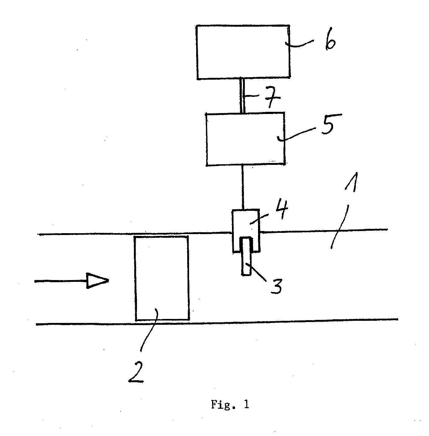
[0026]FIG. 1 is a schematic view of an exhaust duct 1 of a diesel engine in which a particle filter 2 is arranged. The direction of flow of the exhaust gas is indicated by an arrow.

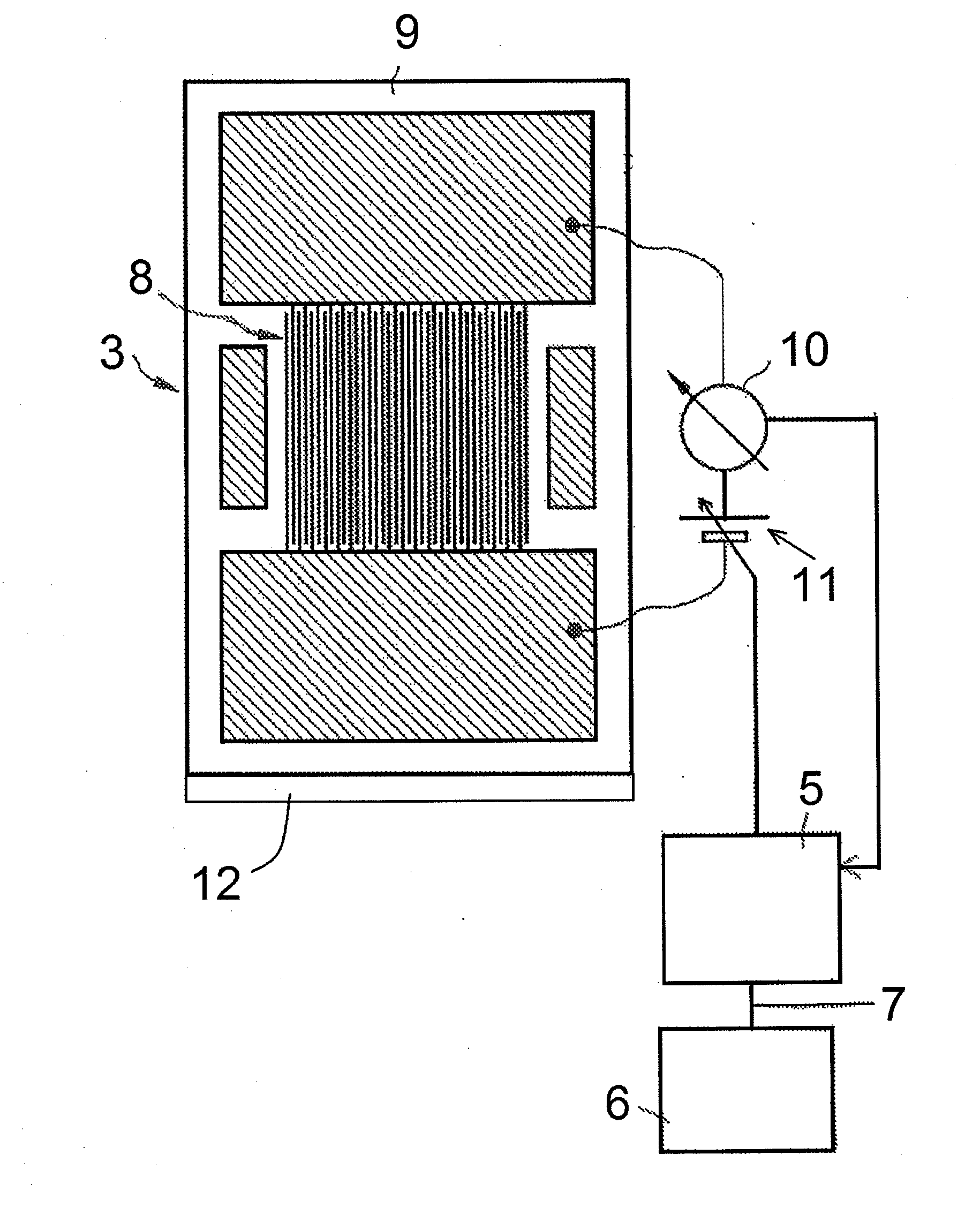
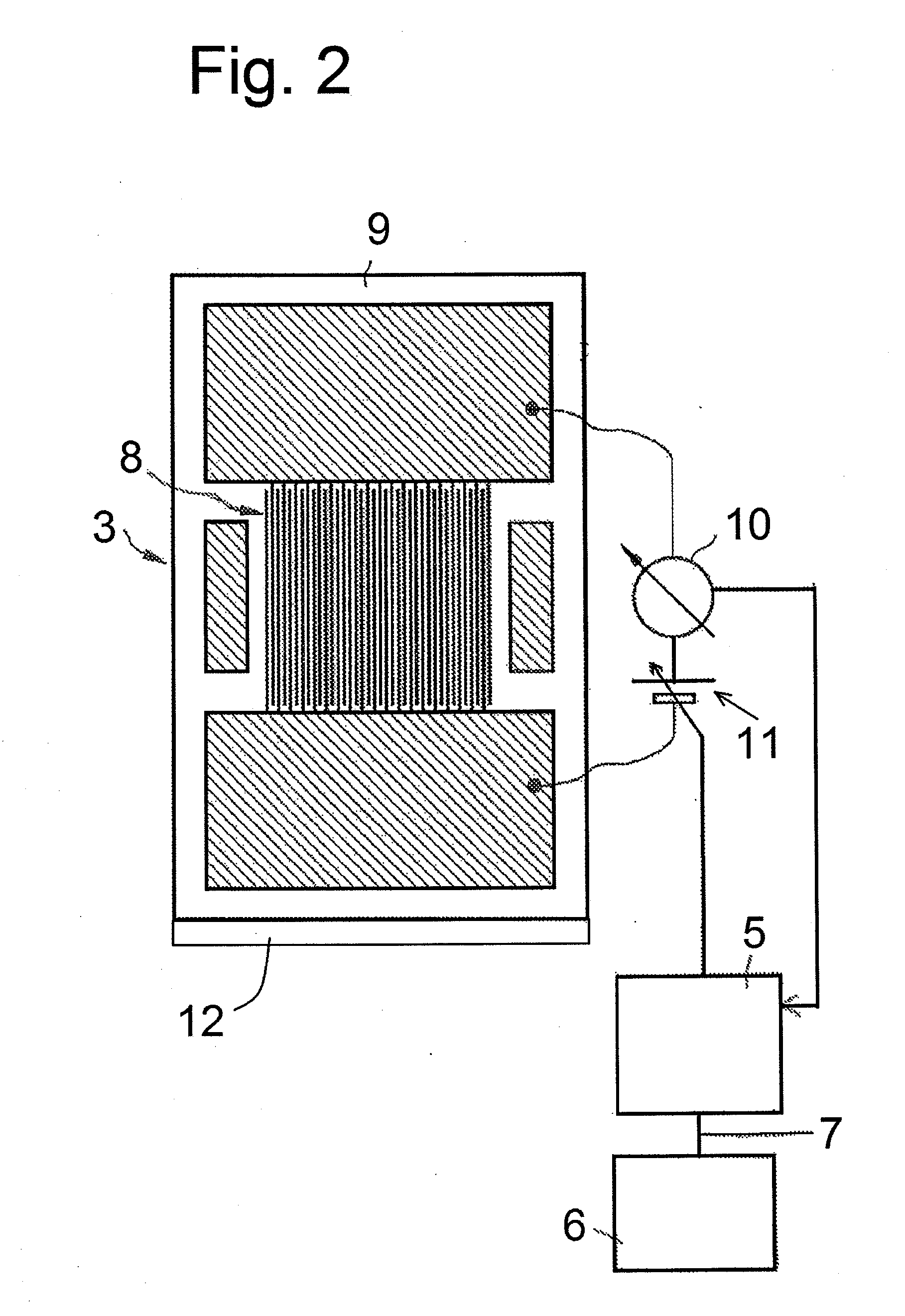
[0027]In order to monitor the functional capability of the particle filter 2, a sensor element 3 is arranged in the exhaust gas duct 1, downstream of the particle filter 2 in the direction of flow, said sensor element 3 being arranged in a high-temperature-resistant screw-in housing 4. The screw-in housing is connected via a suitable cable connection to sensor electronics 5 which are connected to the control unit 6 of the diesel engine via a bidirectional interface 7.

[0028]The sensor element 3 of the soot sensor that comprises the sensor element 3, the screw-in housing 4 and the sensor electronics 5, has an interdigital structure (comb structure) of measuring electrodes and a heater structure on a ceramic strip. The design of such a sensor element is basically known and a further explanation is not requir...


PUM


Abstract

A method and device for measuring the soot load in the exhaust gas systems of diesel engines using a sensor which is mounted downstream of a particulate filter and comprises a sensor element, to measure the operability of the particulate filter. According to the method, the soot load of the sensor element is measured resistively or capacitively using electrodes. The measuring voltage of the sensor element is controlled depending on at least one actual operating parameter of the diesel engine.

Description

CROSS-REFERENCE TO RELATED APPLICATIONS[0001]This is a U.S. national stage of International Application No. PCT / EP2010 / 051157, filed on 1 Feb. 2010. This patent application claims the priority of German Patent Application No. 10 2009 007 126.1, filed 2 February, the entire content of which application is incorporated herein by reference.BACKGROUND OF THE INVENTION[0002]1. Field of the Invention[0003]The present invention relates to a method for measuring the soot load in an exhaust gas system of a diesel engine using a sensor connected downstream of a particle filter having a sensor element as a measure of the functional capability of the particle filter, in which the soot load is measured resistively or capacitively using a sensor element, wherein electrodes are formed on the sensor element and a measurement voltage is applied between the electrodes.[0004]2. Description of the Related Art[0005]Soot sensors, which are used in combination with particle filters in the exhaust gas syst...

Claims


Application Information

Patent Timeline
IPC IPC(8): F01N11/00F01N3/021
CPCF01N9/002F01N11/00F01N2560/05Y02T10/47F02D41/0235F02D41/1466G01N15/0656F01N2570/10Y02T10/40
Inventor ANTE, JOHANNESBIERL, RUDOLFHEINRICH, STEPHANHERRMANN, MARKUSOTT, ANDREASREITMEIER, WILLIBALDSCHÄDLICH, DENNYWEIGL, MANFREDWILDGEN, ANDREAS
Owner EMISENSE TECH
Learn More