Method of making fusible links

a fusible link and link technology, applied in the field of batteries and battery packs, can solve the problems of short circuit, device failure, interfering with the connection between the battery cell and the electrical terminal, etc., and achieve the effect of higher melting temperature and higher electrical resistivity

Active Publication Date: 2012-05-03
SINOELECTRIC POWERTRAIN
View PDF4 Cites 13 Cited by
  • Summary
  • Abstract
  • Description
  • Claims
  • Application Information

AI Technical Summary

Benefits of technology

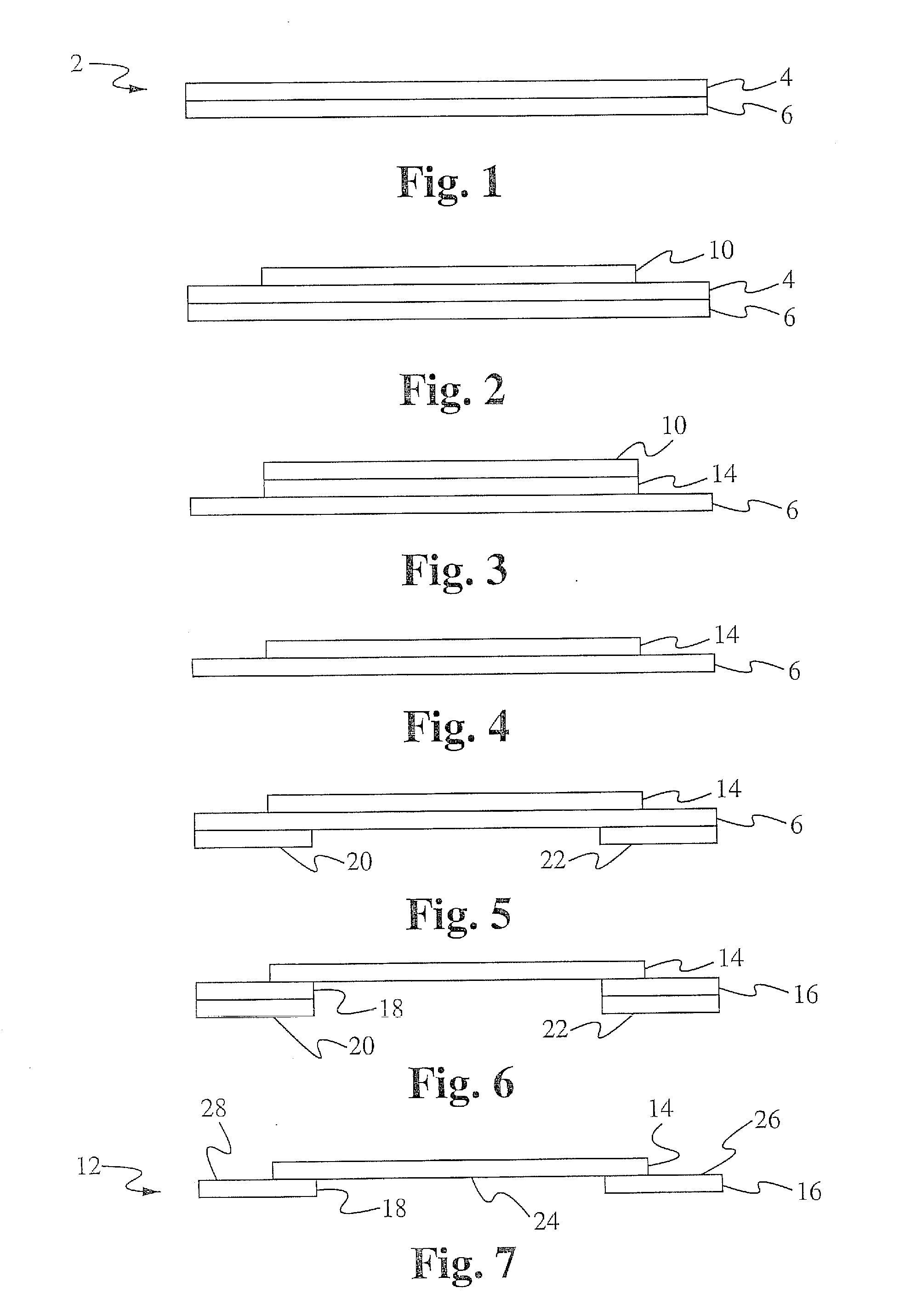
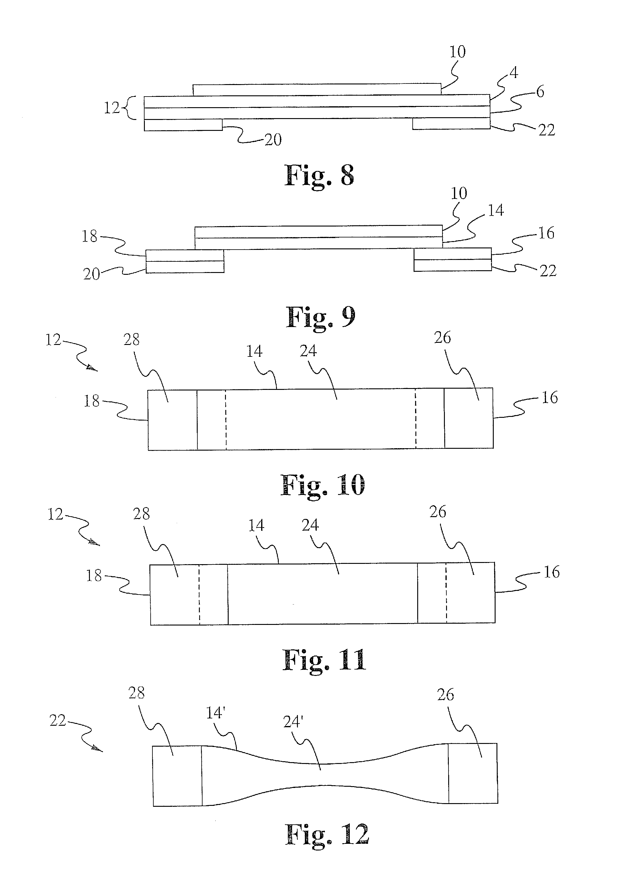
[0009]In one aspect, a method of fabricating one or more fusible links includes providing a clad foil comprising a first layer and a second layer, wherein the first layer and the second layer are made of different materials; applying one or more masks to the first layer and one or more masks to the second layer; selectively etching the first layer and the second layer, thereby forming one or more first portions wherein the first layer is removed and the second layer remains, one or more second portions wherein the first layer is removed and the second layer remains, and one or more third portions wherein the second layer is removed and the first layer remains, wherein each third portion couples one of the first portions to one of the second portions, further wherein each first portion forms a first welding pad and each second portion forms a second welding pad; removing the one or more masks from the first layer; removing the one or more masks from the second layer; and forming one or more fusible conductors from each third portion.
[0010]In some embodiments, the one or more fusible conductors are formed by performing a stamping step or a cutting step on each third portion after the one or more masks are removed from the first layer. In other embodiments, the one or more fusible conductors are formed by etching during the selective etching of the first layer, further wherein the one or more masks applied to the first layer are configured to form the one or more fusible conductors. In some embodiments, the first layer and the second layer are selectively etched using a single-step etching process. In other embodiments, the first layer and the second layer are selectively etched using a two-step etching process, further wherein during a first etching step of the two-step etching process a first etchant is used that etches the first layer but not the second layer, and during a second etching step of the two-step etching process a second etchant is used that etches the second layer but not the first layer. In some embodiments, the clad foil is formed into a single fusible link comprising one first welding pad that forms a battery cell electrode pad, one second welding pad that forms a current collector conductor pad, and one or more fusible conductors coupling the one first welding pad to the one second welding pad. In other embodiments, the clad foil is formed into a fuse sheet having an array of fusible links, each fusible link for coupling to one battery cell electrode of a battery pack. In some embodiments, each third portion is coupled to one of the first welding pads via a first clad foil portion that includes both the first layer and the second layer, and each third portion is coupled to one of the second welding pads via a second clad foil portion that includes both the first layer and the second layer. The second layer has a higher melting temperature and a higher electrical resistivity than the first layer. In some embodiments, the first layer comprises aluminum and the second layer comprises nickel. In some embodiments, each first welding pad comprises a battery cell conductor pad, and each second welding pad comprises a current collector element. In some embodiments, the one or more first welding tabs are welded to battery cell electrodes and the one or more second welding tabs are welded to a current collector plate or to an electrical terminal using resistive welding or laser welding. In some embodiments, the one or more masks applied to the first layer and the one or more masks applied to the second layer are physical masks. In other embodiments, the one or more masks applied to the first layer and the one or more masks applied to the second layer are applied using photolithography. Each fusible conductor opens when a current flow through the fusible conductor reaches a threshold current.
[0011]In another aspect, a method of fabricating a fusible link assembly includes fabricating a fusible link having one or more first welding tabs and welding each of the one or more first welding tabs to a corresponding one battery cell electrode. Fabricating the fusible link includes providing a clad foil comprising a first layer and a second layer, wherein the first layer and the second layer are made of different materials; applying one or more masks to the first layer and one or more masks to the second layer; selectively etching the first layer and the second layer, thereby forming one or more first portions wherein the first layer is removed and the second layer remains, one or more second portions wherein the first layer is removed and the second layer remains, and one or more third portions wherein the second layer is removed and the first layer remains, wherein each third portion couples one of the first portions to one of the second portions, further wherein each first portion forms a first welding pad and each second portion forms a second welding pad; removing the one or more masks from the first layer; removing the one or more masks from the second layer; and forming one or more fusible conductors from each third portion.

Problems solved by technology

The fusible link typically includes a short piece of relatively thin metal wire or strip that melts when excessive current is applied, which interrupts the connection between the battery cell and the electrical terminal.
Short circuit, overload, or device failure is often the reason for excessive current.
However, the wire bonds are very fragile and are rigidly attached to the battery cell and a current collector element.
Under shock and vibration load, especially that seen in electric vehicles utilizing battery packs, the wire bonds are prone to breakage.
This adds manufacturing cost and complexity.
Moreover, this approach loses the ability to service individual battery cells since all battery cells are permanently attached to the current collector element and cannot be reworked.
However, resistive welding and laser welding are not particularly effective when applied to aluminum.
However, ultrasonic welding equipment is more expensive than equipment used for resistive welding and laser welding.
However, nickel has a relatively high electrical resistivity and high melting temperature, especially when compared to aluminum, and as such is not particularly effective for use as a fusible wire bond.

Method used


Image

  • Method of making fusible links
  • Method of making fusible links
  • Method of making fusible links

Examples


Embodiment Construction

[0044]Embodiments of the present application are directed to a fusible link and methods of fabricating thereof. Those of ordinary skill in the art will realize that the following detailed description of the fusible link and fabrication methods are illustrative only and is not intended to be in any way limiting. Other embodiments of the fusible link and fabrication methods will readily suggest themselves to such skilled persons having the benefit of this disclosure.

[0045]Reference will now be made in detail to implementations of the fusible link and fabrication methods as illustrated in the accompanying drawings. The same reference indicators will be used throughout the drawings and the following detailed description to refer to the same or like parts. In the interest of clarity, not all of the routine features of the implementations described herein are shown and described. It will, of course, be appreciated that in the development of any such actual implementation, numerous impleme...


PUM

PropertyMeasurementUnit
fusibleaaaaaaaaaa
melting temperatureaaaaaaaaaa
electrical resistivityaaaaaaaaaa

Abstract

Methods of fabricating the fusible link are directed to processing a multi-layer clad foil having a first layer suitable for forming a fusible link and a second layer suitable for forming one or more welding pads. In some embodiments, the first layer is an aluminum layer and the second layer is a nickel layer. A two-step etching process or a single step etching process is performed on the clad foil to form an etched clad foil having multiple tabs made of the second layer used as current collector conductor pads and battery cell conductor pads, and one or more tabs made of the first layer that form aluminum conductors. The aluminum conductors are shaped and sized to form aluminum fusible conductors during either the etching process or a subsequent stamping process. A single fusible link or an array of fusible links can be formed.

Description

FIELD OF THE INVENTION[0001]The present invention relates to the field of batteries. More particularly, the present invention relates to the field of batteries and battery packs that use fusible links and methods of fabricating the fusible links.BACKGROUND OF THE INVENTION[0002]A battery is a device that converts chemical energy to electrical energy. The battery is a combination of one or more electrochemical cells, each cell consists of two half-cells connected in series by a conductive electrolyte. One half-cell includes electrolyte and an electrode to which negatively-charged ions migrate, for example the anode or negative electrode. The other half-cell includes electrolyte and an electrode to which positively-charged ions migrate, for example the cathode or positive electrode. The electrodes do not touch each other but are electrically connected by the electrolyte. Many cells use two half-cells with different electrolytes. In this configuration, each half-cell is separated by a ...

Claims


Application Information

Patent Timeline
Patent Type & Authority Applications(United States)
IPC IPC(8): C23F1/04H01M50/534H01M50/536
CPCH01H69/022H01H85/046H01H2085/025H01M2/26H01M2200/10Y10T29/49117H01H11/00H01H85/02H05K13/00Y10T29/49107Y10T29/49108H05K1/0293Y02E60/10H01M50/534H01M50/536
Inventor ZHOU, PENGTSAO, PAUL
Owner SINOELECTRIC POWERTRAIN
Why Eureka
Try Eureka