Dynamic control of air interface throughput

a technology of air interface and throughput, applied in the field of radio telecommunication systems, can solve the problems of unfavorable system operation, inability to create new bearers, increased system load, etc., and achieve the effect of maximizing download speed and reducing latency

Inactive Publication Date: 2012-05-03
TELEFON AB LM ERICSSON (PUBL)
View PDF10 Cites 35 Cited by
  • Summary
  • Abstract
  • Description
  • Claims
  • Application Information

AI Technical Summary

Benefits of technology

[0011]The present invention dynamically selects a target delay according to the type of service being utilized. Whenever a user activates a delay-sensitive service, the target delay is dynamically changed to a smaller value to reduce latency. I

Problems solved by technology

The main disadvantage is that it requires the setup of additional bearers in addition to the default bearer, or throughput will be degraded even if Best Effort traffic is present.
For example, it is not possible to create new bearers during periods of high

Method used


Image

  • Dynamic control of air interface throughput
  • Dynamic control of air interface throughput
  • Dynamic control of air interface throughput

Examples


Embodiment Construction

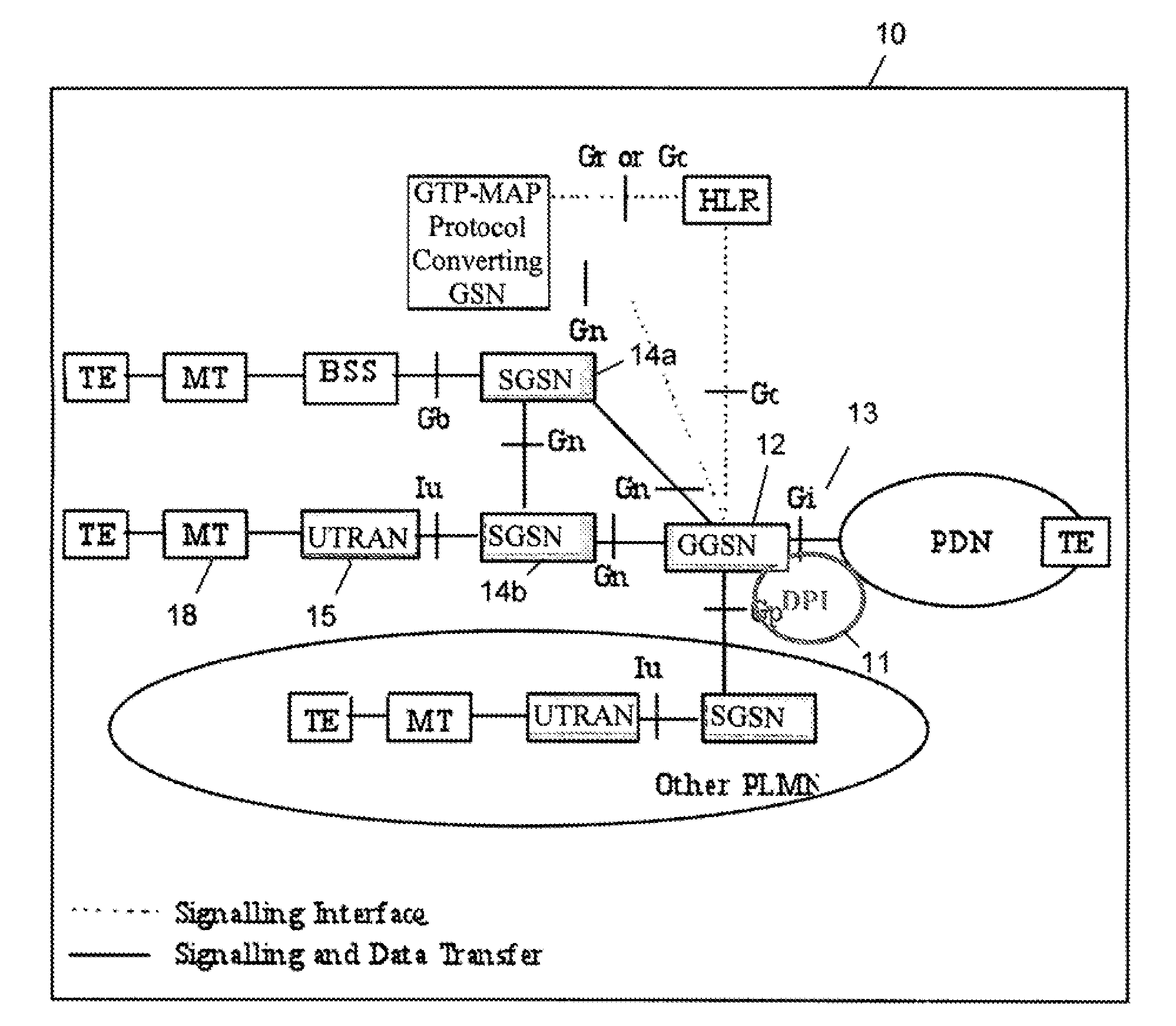
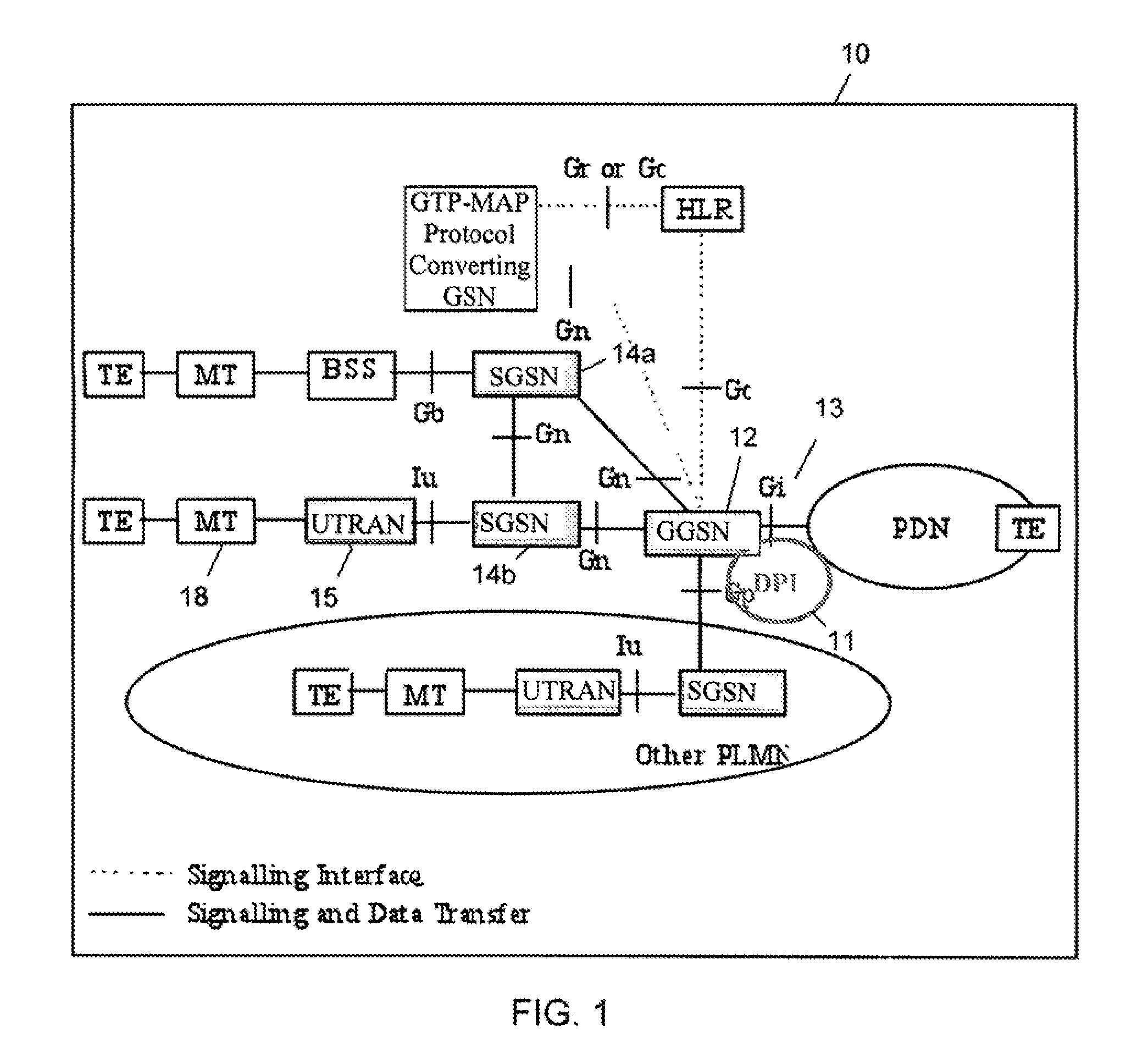
[0026]In order to dynamically select a target delay according to the type of service being utilized, a controlling node must first identify the type of service and its associated flow requirements. In one embodiment, this may be done by defining categories of services, i.e., delay-sensitive (low latency) flow, or throughput-oriented flow. Then, using Deep Packet Inspection (DPI) functionality in a core network node, the user traffic can be analyzed and classified into the categories above.

[0027]After this traffic-identification process is done, the controlling DPI node knows whether the user has delay-sensitive (low latency) traffic or not, and signals the RNC or the HSDPA FC entity in the Node B using per-packet marking within a single bearer. The RNC and the Node B keep multiple (virtual) queues per bearer and selectively put the various marked packet flows into these queues depending on the target delay requirement. Flow control is made aware of the separate queues and it can dif...


PUM


Abstract

A system, method, and network node for dynamically controlling throughput over an air interface between a mobile terminal and a radio telecommunication system. A Gateway GPRS Service Node (GGSN) receives a plurality of traffic flows for the mobile terminal and uses a Deep Packet Inspection (DPI) module to determine a target delay class for each traffic flow. The GGSN signals the target delay class of each traffic flow to a Radio Network Controller (RNC) utilizing per-packet marking within a single radio access bearer (RAB). The RNC defines a separate virtual queue for each delay class on a per-RAB basis, and instructs a Node B serving the mobile terminal to do the same. The Node B services the queues according to packet transmission delays associated with each queue. A flow control mechanism in the Node B sets a packet queue length for each queue to optimize transmission performance.

Description

CROSS-REFERENCE TO RELATED APPLICATIONS[0001]NOT APPLICABLESTATEMENT REGARDING FEDERALLY SPONSORED RESEARCH OR DEVELOPMENT[0002]NOT APPLICABLEREFERENCE TO SEQUENCE LISTING, A TABLE, OR A COMPUTER PROGRAM LISTING COMPACT DISC APPENDIX[0003]NOT APPLICABLEBACKGROUND[0004]The present invention relates to radio telecommunication systems. More particularly, and not by way of limitation, the present invention is directed to a system and method for dynamically controlling throughput over the air interface between a mobile terminal and a radio telecommunication network.[0005]The length of the packet queue (PQ) in a Node-B (base station) is handled by High-Speed Downlink Packet Access (HSDPA) flow control (FC). The flow control process contends with two somewhat contradictory goals: (1) keep the PQ length short for low delay (low latency), which is good for time-sensitive traffic; and (2) keep the PQ length long enough to avoid under-utilization of the available radio bearer, as when there is...

Claims


Application Information

Patent Timeline
IPC IPC(8): H04L12/26
CPCH04L47/14H04L47/2408H04L47/2416H04L47/2441H04L47/2483H04L47/2491H04W28/0252H04W28/0268H04W28/10H04L69/22H04W8/04
Inventor PONGRACZ, GERGELYTURANYI, ZOLTAN RICHARDRACZ, SANDORNADAS, SZILVESZTER
Owner TELEFON AB LM ERICSSON (PUBL)
Why Eureka
Try Eureka