Hydraulic control apparatus for vehicle

a technology of hydraulic control apparatus and vehicle, which is applied in the direction of fluid gearing, instruments, gearings, etc., can solve the problems of clutch deterioration, clutch is prone to be in a fully disengaged state, and engagement shocks, so as to reduce the occurrence of clutch engagement shocks and improve the accuracy of clutch control

Active Publication Date: 2012-05-03
JATCO LTD +1
View PDF11 Cites 13 Cited by
  • Summary
  • Abstract
  • Description
  • Claims
  • Application Information

AI Technical Summary

Benefits of technology

[0003]During execution of the WSC control, when a driver depresses a brake pedal and the vehicle is in a vehicle stop state, since the slip-engagement of a clutch (the second brake) is held unchanged, the clutch generates heat, and this leads to deterioration of the clutch. In order to suppress the heat generation of the clutch, an input torque to the clutch can be reduced. Thus, to reduce the input torque, it is conceivable that a transmission torque capacity of the clutch can be reduced. In order to reduce the transmission torque capacity of the clutch, a hydraulic pressure that engages the clutch is decreased. However, at this time, a feedback control is performed so that an actual hydraulic pressure agrees with a command hydraulic pressure.
[0007]For these problems, it is therefore an object of the present invention to provide a hydraulic control apparatus for the vehicle, which is capable of improving the accuracy of the clutch control and reducing the occurrence of the clutch engagement shock at the vehicle start while suppressing the heat generation of the clutch in the control range where the transmission torque capacity of the clutch (a frictional engagement element) is low.
[0009]According to another aspect of the invention, a method for controlling an engagement hydraulic pressure provided to a frictional engagement element that is arranged between a driving source and a driving wheel and connects / disconnects a torque transmitted between the driving source and the driving wheel in a vehicle, has: calculating a target engagement hydraulic pressure of the frictional engagement element; controlling the frictional engagement element so that a revolution speed at a driving source side of the frictional engagement element is a higher revolution speed than a revolution speed at a driving wheel side of the frictional engagement element; outputting a command current to a solenoid valve that controls the engagement hydraulic pressure provided to the frictional engagement element on the basis of a map that has a relationship between the target engagement hydraulic pressure and the command current; decreasing the engagement hydraulic pressure provided to the frictional engagement element when a vehicle speed is equal to or less than a predetermined vehicle speed at which the vehicle is judged to be vehicle stop during execution of the slip control, and correcting the map so that a variation of the command current with respect to a variation of the target engagement hydraulic pressure is small when decreasing the engagement hydraulic pressure.

Problems solved by technology

During execution of the WSC control, when a driver depresses a brake pedal and the vehicle is in a vehicle stop state, since the slip-engagement of a clutch (the second brake) is held unchanged, the clutch generates heat, and this leads to deterioration of the clutch.
Because of this, in the case where the control is performed so as to decrease the engagement hydraulic pressure of the clutch during the execution of the WSC control, even if the feedback control is carried out, the clutch is prone to be in a fully disengaged state.
Thus, there is a possibility that an engagement shock will occur at this clutch state shift.
On the other hand, in the case where the control is performed so that the engagement hydraulic pressure of the clutch is higher in order to prevent the clutch from being in the fully disengaged state, the input torque of the clutch becomes large, then the heat generation of the clutch can not be suppressed.

Method used


Image

  • Hydraulic control apparatus for vehicle
  • Hydraulic control apparatus for vehicle
  • Hydraulic control apparatus for vehicle

Examples


embodiment 1

[Drive System]

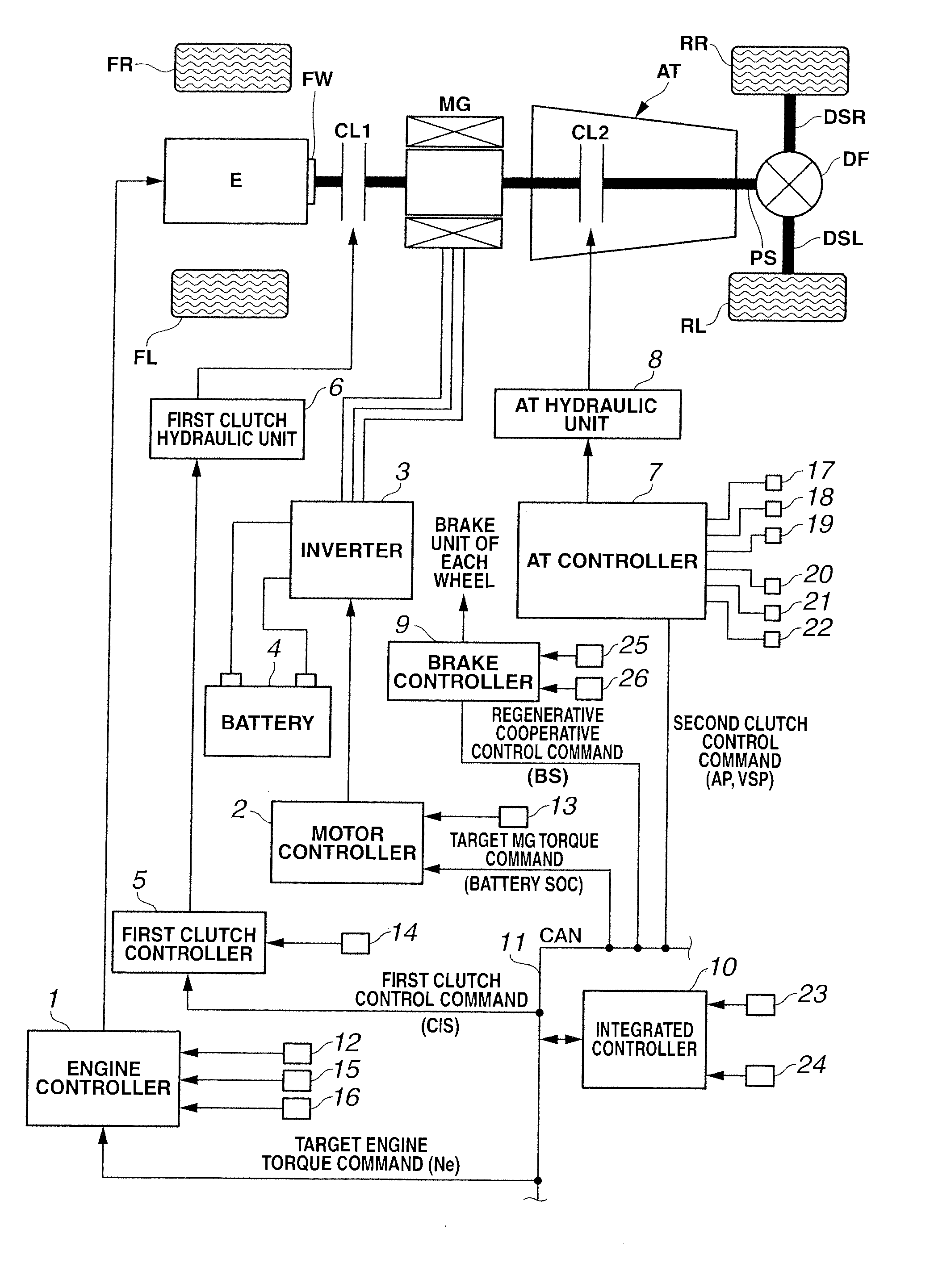
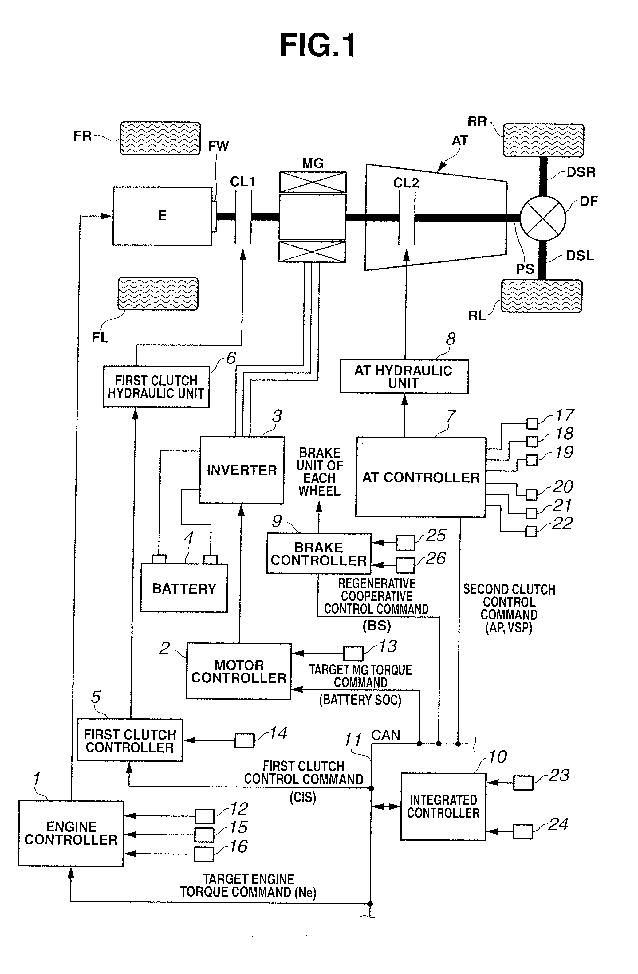
[0026]First, a drive system of a hybrid vehicle will be explained. FIG. 1 is a whole system block diagram showing a rear-drive hybrid vehicle of the embodiment 1.

[0027]The drive system of the hybrid vehicle in the embodiment 1 has an engine E, a first clutch CL1, a motor / generator MG, a second clutch CL2, an automatic transmission AT, a propeller shaft PS, a differential gear DF, a left drive shaft DSL, a right drive shaft DSR, a rear left wheel RL (driving wheel), and a rear right wheel RR (driving wheel). Needless to say, FL is a front left wheel, and FR is a front right wheel.

[0028]The engine E is, for instance, a gasoline engine, and a valve opening of throttle valve etc. is controlled on the basis of a control command from an after-mentioned engine controller 1. As shown in FIG. 1, a flywheel FW is provided at an engine output shaft.

[0029]The first clutch CL1 is a clutch that is arranged between the engine E and the motor / generator MG. Engagement / slip-engagement / d...


PUM


Abstract

The hydraulic control apparatus calculates a target engagement hydraulic pressure of a frictional engagement element, controls the frictional engagement element so that a revolution speed at a driving source side of the frictional engagement element is higher than a revolution speed at a driving wheel side of the frictional engagement element, outputs a command current to a solenoid valve on the basis of a map having a relationship between the target engagement hydraulic pressure and the command current, and decreases the engagement hydraulic pressure when a vehicle speed is equal to or less than a predetermined vehicle speed at which the vehicle is judged to be vehicle stop during execution of the slip control. Further, the hydraulic control apparatus corrects the map so that a variation of the command current with respect to a variation of the target engagement hydraulic pressure is small when decreasing the engagement hydraulic pressure.

Description

BACKGROUND OF THE INVENTION[0001]The present invention relates to a hydraulic control apparatus for a vehicle.[0002]As a hydraulic control apparatus, for example, it is disclosed in Japanese Patent Provisional Publication No. 2010-77981 (hereinafter is referred to as “JP2010-77981”). JP2010-77981 discloses a WSC control that starts the vehicle while controlling an output torque of driving force by slip-engaging a second brake after judging an initiation of engagement of a starting frictional element.SUMMARY OF THE INVENTION[0003]During execution of the WSC control, when a driver depresses a brake pedal and the vehicle is in a vehicle stop state, since the slip-engagement of a clutch (the second brake) is held unchanged, the clutch generates heat, and this leads to deterioration of the clutch. In order to suppress the heat generation of the clutch, an input torque to the clutch can be reduced. Thus, to reduce the input torque, it is conceivable that a transmission torque capacity of ...

Claims


Application Information

Patent Timeline
Patent Type & Authority Applications(United States)
IPC IPC(8): B60W10/02B60W30/18
CPCB60W10/02B60W2510/0241B60W20/00B60W30/18063B60W30/181B60W30/186B60W2520/04B60W2520/10B60W2540/10B60W2710/023B60W2710/025Y10T477/755B60W20/11B60W20/40B60W10/115F16H45/02
Inventor MOCHIYAMA, SHINYAYAMAMOTO, HIDEHARU
Owner JATCO LTD
Why Eureka
Try Eureka