Method for Determining a Pressure at the Output of an Exhaust Gas System

a technology of exhaust gas and output pressure, which is applied in the direction of electrical control, instruments, machines/engines, etc., can solve the problems of system robustness, significant interference, and interference with exhaust gas measurement technology, and achieve simple and more precise manner of determining throttling, high accuracy, and simple

Active Publication Date: 2012-05-03
VOLKSWAGEN AG
View PDF7 Cites 4 Cited by
  • Summary
  • Abstract
  • Description
  • Claims
  • Application Information

AI Technical Summary

Benefits of technology

[0019]A plurality of pressures may be determined one after the other at the output of the exhaust gas system at different settings of the throttle valve, the high-pressure exhaust-gas recirculation valve and the low-pressure exhaust-gas recirculation valve. The pressure at the output of the exhaust gas system is determined from the plurality of pressures, for instance by averaging. When implementing the pressure at the output of the exhaust gas system at different settings of the valves and the throttle valve, errors, such as with regard to the throttling of the mass flow through the correspondingly configured internal combustion engine system, or ...

Problems solved by technology

However, in systems which are optimized with regard to flow losses there are problems with the overall system regarding the robustness of the metering of the low-pressure exhaust-gas recirculation gas.
For example, if such a system is operated on an engine test stand or a chassis dynometer, such as for certification purposes, the exhaust-gas measuring technology creates interference.
This vacuum pressure may even cause fresh air from an intake region downstream from the compressor to reach the exhaust gas system directly through the low-pressure exhaust-gas recirculation component.
Even a slight fault in the exhaust-...

Method used


Image

  • Method for Determining a Pressure at the Output of an Exhaust Gas System
  • Method for Determining a Pressure at the Output of an Exhaust Gas System

Examples


Embodiment Construction

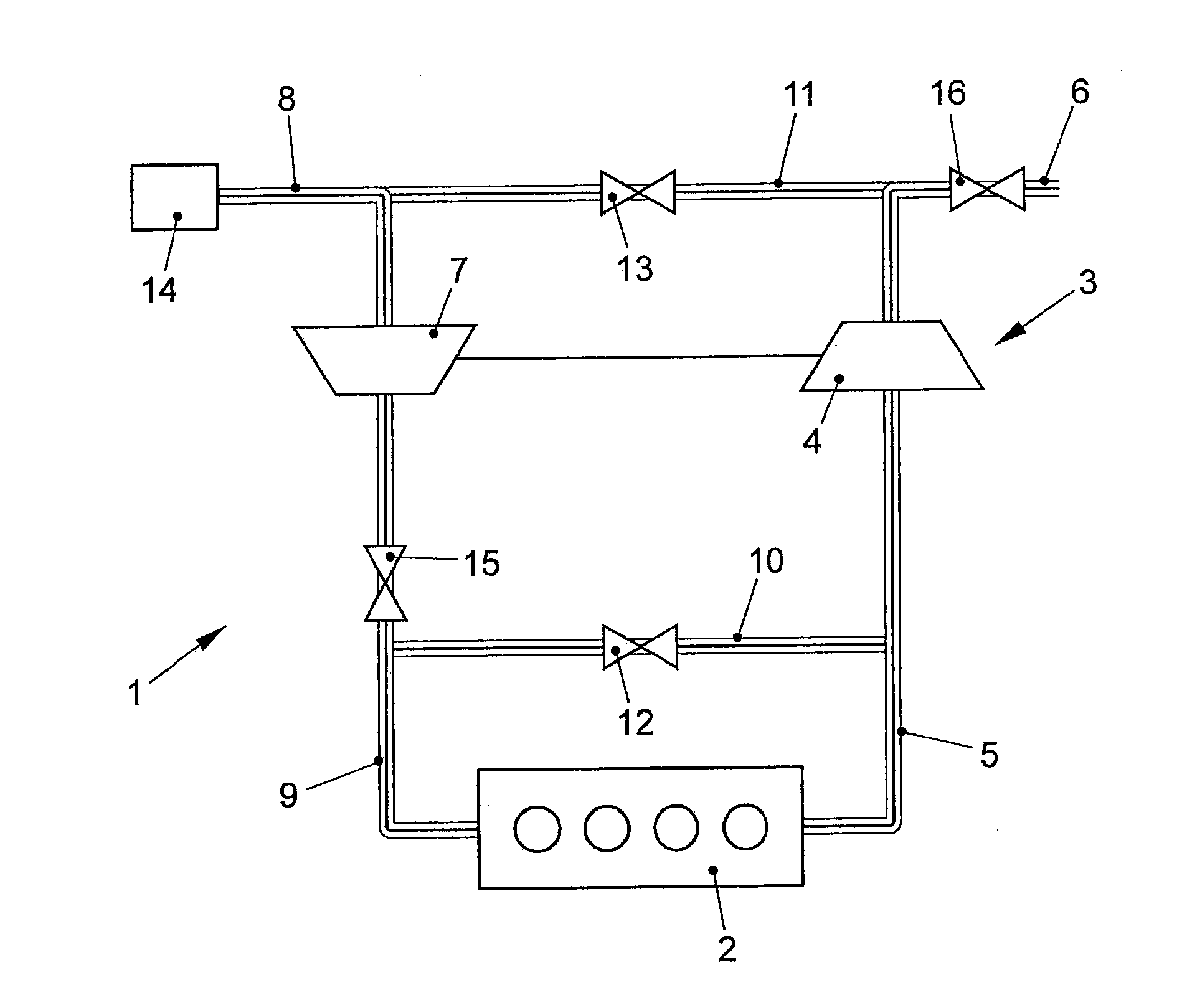
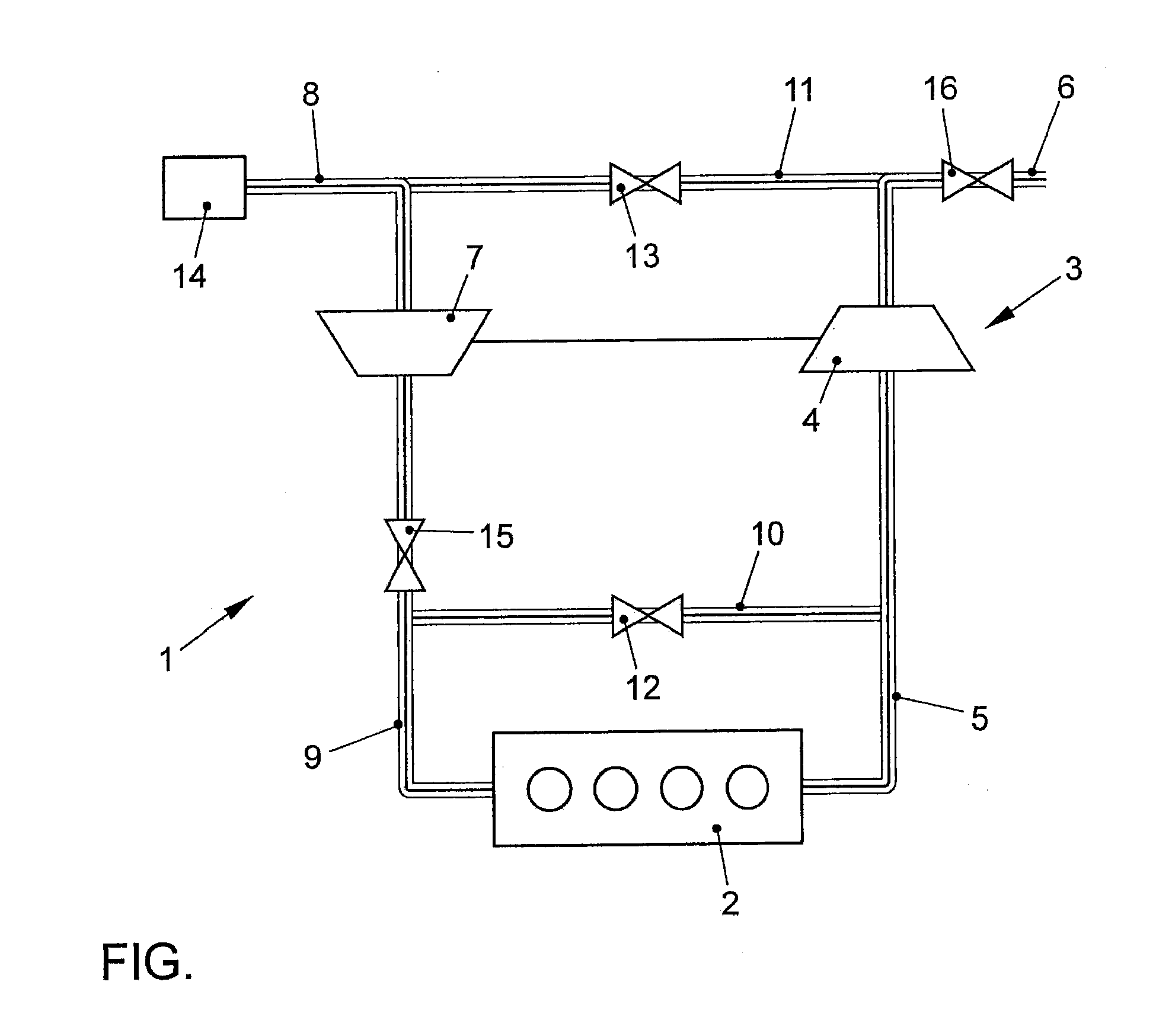
[0027]The FIGURE schematically shows an internal combustion engine system 1 which includes an internal combustion engine 2 and an exhaust-gas turbocharger 3. Exhaust-gas turbocharger 3 has a turbine 4, which is disposed between an exhaust-gas output 5 of internal combustion engine 2 and an exhaust gas system 6 of internal combustion engine system 1. In addition, exhaust-gas turbocharger 3 includes a compressor 7, which is mechanically linked to turbine 4 and disposed between a fresh air supply 8 and an intake manifold 9 of internal combustion engine 2. Internal combustion engine system 1 furthermore includes a high-pressure exhaust-gas recirculation component 10 and a low-pressure exhaust-gas recirculation component 11. High-pressure exhaust-gas recirculation component 10 couples exhaust-gas output 5 to intake manifold 9 and includes a high-pressure exhaust-gas recirculation valve 12, which is able to influence a mass flow through high-pressure exhaust-gas recirculation component 10...


PUM


Abstract

In a method for determining a pressure at the output of an exhaust gas system of an internal combustion engine system of a vehicle, a mass flow through the internal combustion engine system and an ambient pressure at a fresh air supply of the internal combustion engine system are detected. The pressure at the output of the exhaust gas system is determined as a function of the mass flow, the ambient pressure and throttling of the mass flow through the internal combustion engine system.

Description

CROSS-REFERENCE TO RELATED APPLICATIONS[0001]The present application claims priority to Application No. 10 2010 050 161.1, filed in the Federal Republic of Germany on Oct. 30, 2010, which is expressly incorporated herein in its entirety by reference thereto.FIELD OF THE INVENTION[0002]The present invention relates to a method for determining a pressure at the output of an exhaust gas system of an internal combustion engine system of a vehicle, especially an internal combustion engine system having an exhaust-gas turbocharger and a high-pressure exhaust-gas recirculation component as well as a low-pressure exhaust-gas recirculation component.BACKGROUND INFORMATION[0003]Internal combustion engine systems such as Diesel engines use exhaust-gas recirculation components to return a portion of the combustion gases of the internal combustion engine to a fresh-air supply of the internal combustion engine, in order to resupply this portion of the combustion waste gas together with fresh air ...

Claims


Application Information

Patent Timeline
IPC IPC(8): F02D9/02F02D28/00
CPCF02D41/0072F02D41/145F02D41/2474F02D2041/1433F02D2200/0402F02D2200/703Y02T10/47F02M26/05F02M26/06Y02T10/40
Inventor JESCHKE, JENS
Owner VOLKSWAGEN AG
Why Eureka
Try Eureka