Rotational angle detection device
- Summary
- Abstract
- Description
- Claims
- Application Information
AI Technical Summary
Benefits of technology
Problems solved by technology
Method used
Image

Examples
first embodiment
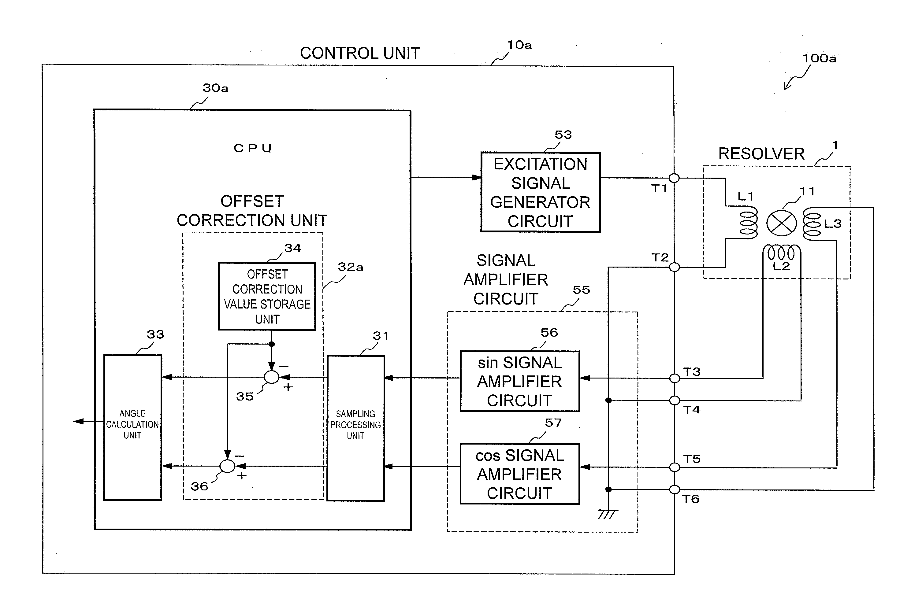
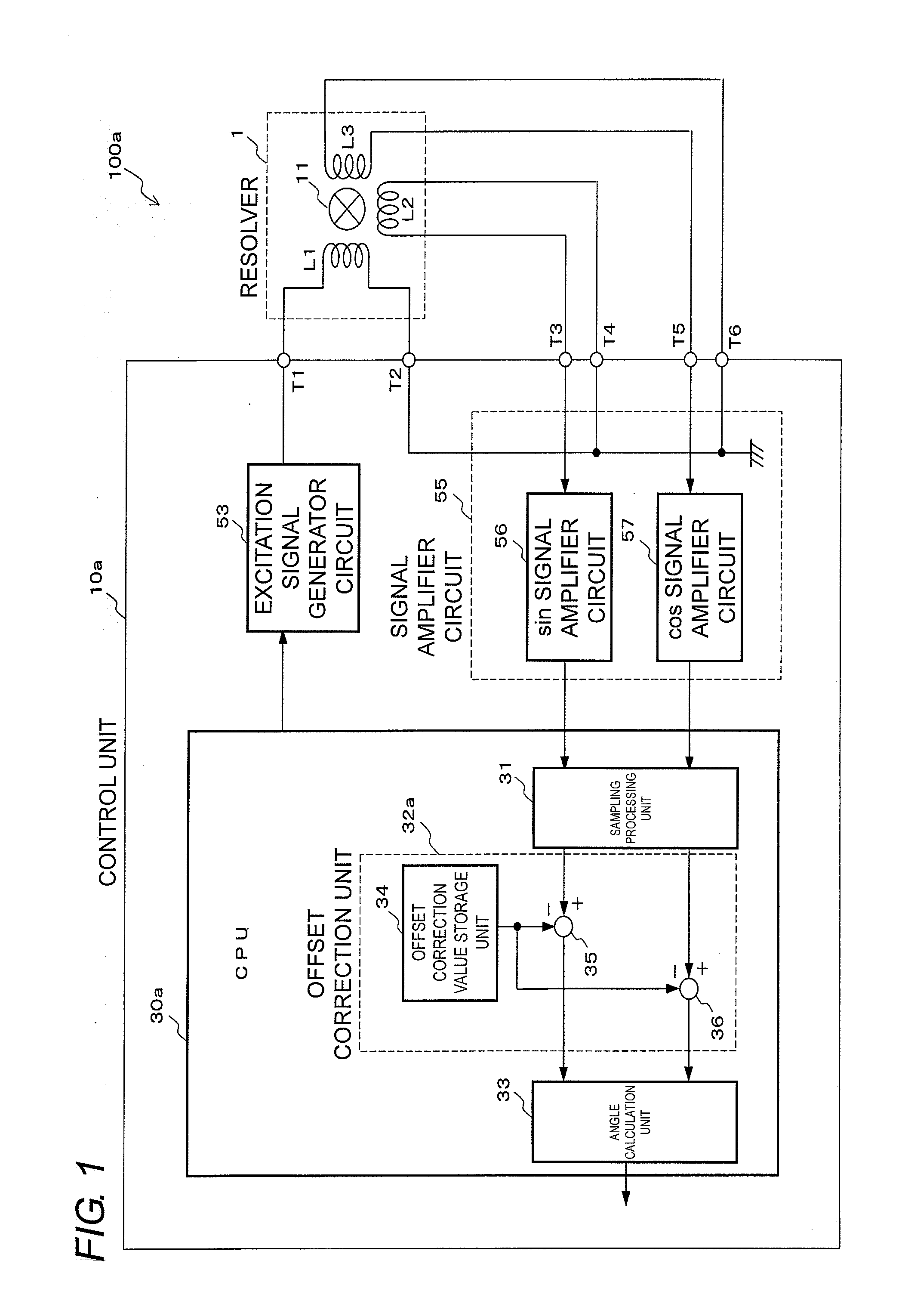
[0044]FIG. 1 is a block diagram of a rotational angle detection device according to the present invention. A rotational angle detection device 100a is composed of a resolver 1 and a control unit 10a. The resolver 1 is the same as that described with reference to FIGS. 6 and 7, and accordingly, a description thereof is omitted here, and a description is made below of details of the control unit 10a.
[0045]The control unit 10a includes an excitation signal generator circuit 53, a signal amplifier circuit 55 and a CPU 30a. In the control unit 10a, the inverted excitation signal generator circuit 54 of FIG. 9 is not provided, and only the excitation signal generator circuit 53 is provided. In other words, this rotational angle detection device 100a is a rotational angle detection device of a single excitation mode, which generates a single excitation signal by using the one excitation signal generator circuit 53.
[0046]An output (excitation signal) of the excitation signal generator circ...
second embodiment
[0070]FIG. 5 is a block diagram of a rotational angle detection device according to the present invention. A rotational angle detection device 100b is composed of a resolver 1 and a control unit 10b. The resolver 1 is the same as that described with reference to FIGS. 6 and 7, and accordingly, a description thereof is omitted here. Moreover, an excitation signal generator circuit 53 and a signal amplifier circuit 55 in the control unit 10b are the same as those in FIG. 1, and a description thereof is also omitted. A description is made below of a CPU 30b.
[0071]In an offset correction unit 32b of the CPU 30b, an offset correction value arithmetic operation unit 37 is provided in place of the offset correction value storage unit 34 shown in FIG. 1. Other configurations of the CPU 30b are the same as those of the CPU 30a of FIG. 1. The offset correction value arithmetic operation unit 37 arithmetically operates an offset correction value based on the respective sampling signals to be ...
PUM
 Abstract
Description
Claims
Application Information
 - R&D
- Intellectual Property
- Life Sciences
- Materials
- Tech Scout
- Unparalleled Data Quality
- Higher Quality Content
- 60% Fewer Hallucinations
Browse by: Latest US Patents, China's latest patents, Technical Efficacy Thesaurus, Application Domain, Technology Topic, Popular Technical Reports.
© 2025 PatSnap. All rights reserved.Legal|Privacy policy|Modern Slavery Act Transparency Statement|Sitemap|About US| Contact US: help@patsnap.com