Engine System with Reformer

a technology of engine system and reformer, which is applied in the direction of machines/engines, output power, combustion air/fuel air treatment, etc., can solve the problems of enlarging the reformer and difficult to achieve high reforming efficiency, and achieve the effect of reducing the size of the reformer and enhancing the reformer efficiency

Inactive Publication Date: 2012-05-10
HITACHI LTD
View PDF4 Cites 7 Cited by
  • Summary
  • Abstract
  • Description
  • Claims
  • Application Information

AI Technical Summary

Benefits of technology

[0007]According to the present invention, since a part of the exhaust gas can be trapped in a space between the reformer and an engine chamber by closing the control valve during an exhaust stroke, the reforming efficiency of the reformer can be heightened. Thereby, since reformed gas of predetermined amount is permitted to be produced in the reformer, the size of the reformer can be reduced.

Problems solved by technology

In the system as disclosed in patent document 1, since the temperature of exhaust gas fed to the reformer lowers during low output operating conditions such as idling and low speed operation, it is difficult to obtain a high reforming efficiency.
For this reason, it is necessary to increase contacting area between exhaust gas and the reformer for heightening the reforming efficiency in a broad operating range, which arises a problem of enlarging the reformer.

Method used


Image

  • Engine System with Reformer
  • Engine System with Reformer
  • Engine System with Reformer

Examples


Embodiment Construction

[0011]Herein below, embodiments according to the present invention will be explained with reference to the drawings.

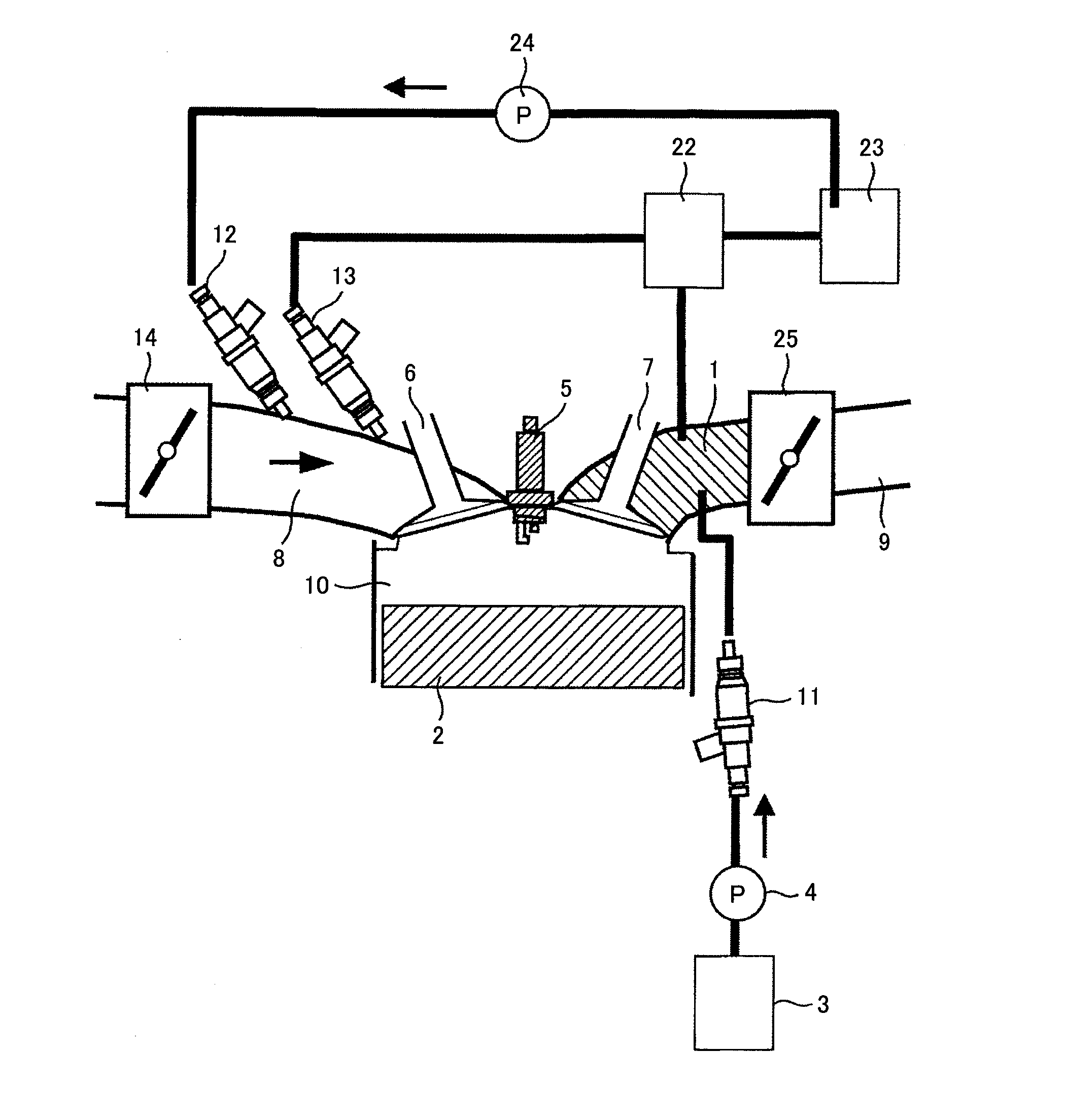
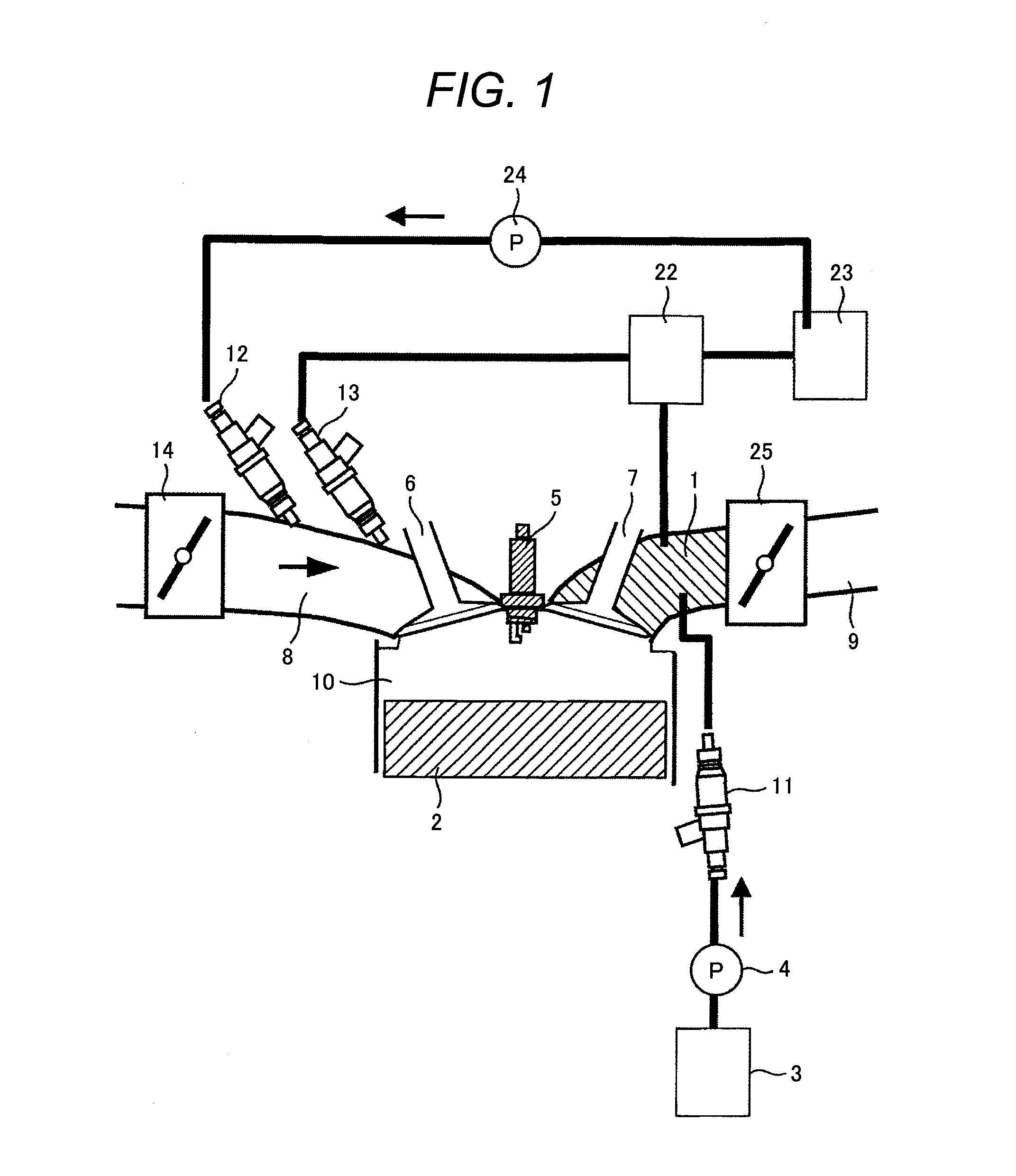
[0012]FIG. 1 is a constitutional diagram of the present system. In the present system, a reformer 1 is disposed in an exhaust pipe 9 near an exhaust valve 7. With regard to the position in the exhaust pipe 9 where the reformer 1 is provided, the reformer 1 is installed either at an engine head near the exhaust valve 7 or just downstream from the engine head in the exhaust pipe. Further, a control valve 25 for controlling a flow rate of the exhaust gas is disposed downstream from the installed position of the reformer in the exhaust pipe 9 where the reformer 1 is disposed. Pre-reformed fuel is filled in a pre-reformed fuel tank 3, and it is fed to the reformer1 from a pre-reformed fuel control device 11 via a pre-reformed fuel pump 4. Post-reformed fuel having been reformed with the reformer 1 is separated into hydrogen rich gas and dehydrogenated fuel by a gas-liquid s...


PUM


Abstract

In an engine system with a reformer being installed in an exhaust pipe to reform a fuel, a control valve for controlling a flow rate of exhaust gas is provided downstream from an installed position of the reformer in the exhaust pipe. In the engine system with the reformer, since a part of the exhaust gas can be trapped in a space between the reformer and an engine chamber by closing the control valve during an exhaust stroke, the reforming efficiency of the reformer can be heightened.

Description

FIELD OF THE INVENTION[0001]The present invention relates to an engine system with a reformer.BACKGROUND ART[0002]In a system for producing hydrogen or the like from a fuel by reforming the fuel to be fed into an engine, it is expected to enhance hydrogen producing efficiency because it makes an exhaust heat recovery system of reforming the fuel with an endothermic reaction of the fuel by making use of engine exhaust heat. Further, in a system of reforming a hydrocarbon fuel such as gasoline to produce hydrogen from the fuel and feeding a resultant gas as reformed gas including the hydrogen to an internal combustion engine, it is expected to heighten engine efficiency because it provides a way for the engine to make such as reduction of pumping loss, enhancement of combustion efficiency and enhancement of combustion speed. In a system where a reformer is installed in an exhaust pipe of an internal combustion engine, since exhaust gas temperature of the engine varies depending on eng...

Claims


Application Information

Patent Timeline
Patent Type & Authority Applications(United States)
IPC IPC(8): F02M25/07
CPCC01B3/32F01N2240/30F02D9/04Y02T10/18F02M25/12F02M27/02Y02T10/121F02D13/0234Y02T10/12
Inventor SHIMADA, ATSUSHIISHIKAWA, TAKAOSANO, TADASHI
Owner HITACHI LTD
Why Eureka
Try Eureka