
In-situ vaporizer and recuperator for alternating flow device

a heat recovery apparatus and vaporizer technology, applied in lighting and heating apparatus, combustion types, roads, etc., can solve the problems of difficult vapor stream handling, poor transient operation, and significant thermal mass of traditional vaporizers and boilers,

Inactive Publication Date: 2012-05-10
EXXON RES & ENG CO
View PDF6 Cites 21 Cited by
  • Summary
  • Abstract
  • Description
  • Claims
  • Application Information

AI Technical Summary

Benefits of technology

[0005]The present inventors have discovered particular design criteria of such an in-situ vaporizer and heat recovery device that are required for it to achieve the above described advantages. These features include specifications on geometry, heat capacity and heat transfer, flow channel dimensions, and void fraction and void fraction gradient to minimize the size and weight of the device. A unique combination of these design criteria produce a high efficiency vaporizer / recuperator as demonstrated in an application to pressure swing reforming as taught in the above referenced patent.

Problems solved by technology

Traditional vaporizers and boilers require significant thermal mass and generally perform poorly in transient operation due to fluctuating pressure and temperature changes.
For mobile applications, the transient requirements to operate over a wide dynamic operating range (known as turndown) makes vapor stream handling difficult and provides challenges for equivalence ratio control between fuel and oxidizer.

Method used


Image

  • In-situ vaporizer and recuperator for alternating flow device
  • In-situ vaporizer and recuperator for alternating flow device
  • In-situ vaporizer and recuperator for alternating flow device

Examples


Embodiment Construction

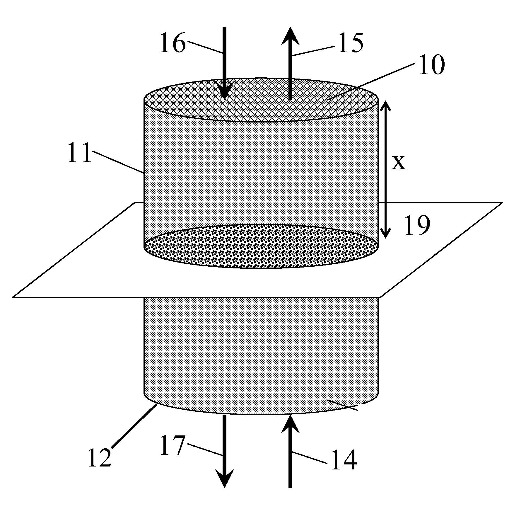
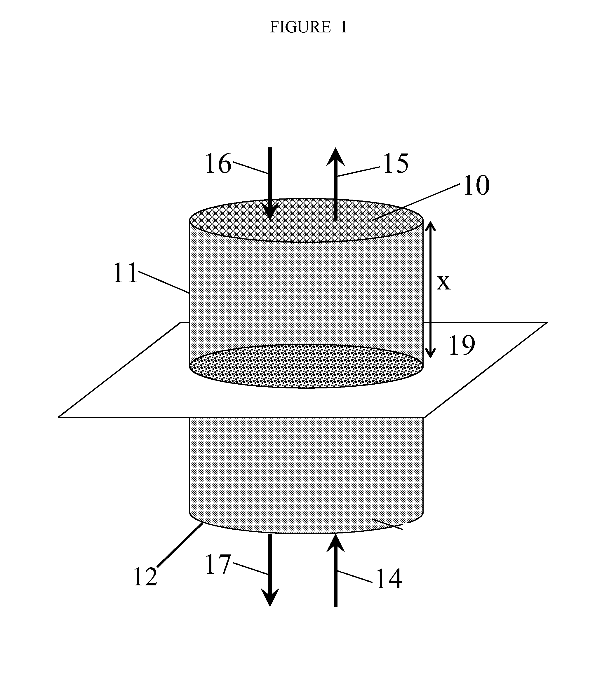
[0011]The present invention is directed to a device for converting a supplied liquid stream(s) to a gaseous vapor stream. More particularly, the invention relates to a device operating in a cyclic process whereby a liquid hydrocarbon and, optionally, a water mixture is converted into a mixture of hydrocarbon vapor and optionally steam. One particular application is for vaporization of a liquid hydrocarbon and water stream for use in a pressure swing steam reforming process.

[0012]The device is designed for continuous operation through a cyclic two-stage process. The first stage is a vaporization mode, and the second stage is a reheating mode. We have discovered particular design criteria or features that produce an in-situ vaporizer and heat recovery device capable of large dynamic ranges of operation, minimal pressure drop, corrosion resistance, and be sufficiently compact and light weight for mobile applications. These features include specifications on geometry, heat capacity and ...


PUM

PropertyMeasurementUnit
Poweraaaaaaaaaa
Poweraaaaaaaaaa
Poweraaaaaaaaaa

Abstract

The present invention relates to a device for converting a liquid feed stream to a gaseous vapor stream comprising: (a) channel means having a first and second end, said channel means having a plurality of channels connecting said first and second end, said channel means having a substantially solid region and a void region, (b) inlet means for directing the liquid feed stream to the first end of the plurality of channels, and (c) outlet means for directing the gaseous vapor stream from said plurality of channels, where said channels have, at any distance d between the inlet and outlet, a geometric configuration, perpendicular to the feed flow direction, wherein the average void fraction ranges from about 0.3 to about 0.95.

Description

CROSS-REFERENCE TO RELATED APPLICATIONS[0001]This application claims the benefit of provisional U.S. Application No. 61 / 411,512, filed Nov. 9, 2010, the contents of which are incorporated herein by reference.FIELD OF THE INVENTION[0002]The present invention relates to an in situ vaporizer and heat recovery apparatus for an alternating flow system that can be located on-board a transportation vehicle.BACKGROUND OF THE INVENTION[0003]Many industrial processes, including steam reforming, often require the conversion of liquid feed streams (such as gasoline or other liquid hydrocarbons, or water) to vapor streams prior to chemical conversion. Traditional vaporizers and boilers require significant thermal mass and generally perform poorly in transient operation due to fluctuating pressure and temperature changes. For mobile applications, the transient requirements to operate over a wide dynamic operating range (known as turndown) makes vapor stream handling difficult and provides challen...

Claims


Application Information

Patent Timeline
IPC IPC(8): F24H1/10
CPCF23K5/22Y02E60/324B01J19/0093B01J19/249B01J2219/00783B01J2219/0079B01J2219/00797B01J2219/00822B01J2219/00835B01J2219/0086B01J2219/00873B01J2219/2453B01J2219/2454B01J2219/2459B01J2219/2466B01J2219/247B01J2219/2477B01J2219/2485B01J2219/2497C01B3/46C01B2203/0233C01B2203/0822C01B2203/1276C01B2203/1288B01B1/005Y02P20/10B01B1/00B01J8/06B01J19/24F23D3/00Y02E60/32
Inventor GRENDA, JEFFREY M.HERSHKOWITZ, FRANK
Owner EXXON RES & ENG CO
Learn More