Polycrystalline compacts including nanoparticulate inclusions, cutting elements and earth-boring tools including such compacts, and methods of forming same

a technology of polycrystalline compacts and nanoparticulate inclusions, applied in the field of polycrystalline compacts, can solve the problems of diamond table thermal damage, diamond table delaminate from the substrate, and relatively large compressive and tensile stresses

Active Publication Date: 2012-05-10
BAKER HUGHES INC
View PDF4 Cites 35 Cited by
  • Summary
  • Abstract
  • Description
  • Claims
  • Application Information

AI Technical Summary

Problems solved by technology

The presence of the catalyst material in the diamond table may contribute to thermal damage in the diamond table when the cutting element is heated during use, due to friction at the contact point between the cutting element and the formation.
This differential in thermal expansion rates may result in relatively large compressive and tensile stresses at the interface between the diamond table and the substrate, and may cause the diamond table to delaminate from the substrate.
For example, cobalt thermally expands significantly faster than diamond, which may cause cracks to form and propagate within the diamond table, eventually leading to deterioration of the diamond table and ineffectiveness of the cutting element.
For example, the diamond crystals may graphitize at the diamond crystal boundaries, which may substantially weaken the diamond table.
It has also been reported, however, that such fully leached diamond tables are relatively more brittle and vulnerable to shear, compressive, and tensile stresses than are non-leached diamond tables.
In addition, it is difficult to secure a completely leached diamond table to a supporting substrate.

Method used


Image

  • Polycrystalline compacts including nanoparticulate inclusions, cutting elements and earth-boring tools including such compacts, and methods of forming same
  • Polycrystalline compacts including nanoparticulate inclusions, cutting elements and earth-boring tools including such compacts, and methods of forming same
  • Polycrystalline compacts including nanoparticulate inclusions, cutting elements and earth-boring tools including such compacts, and methods of forming same

Examples


embodiment 1

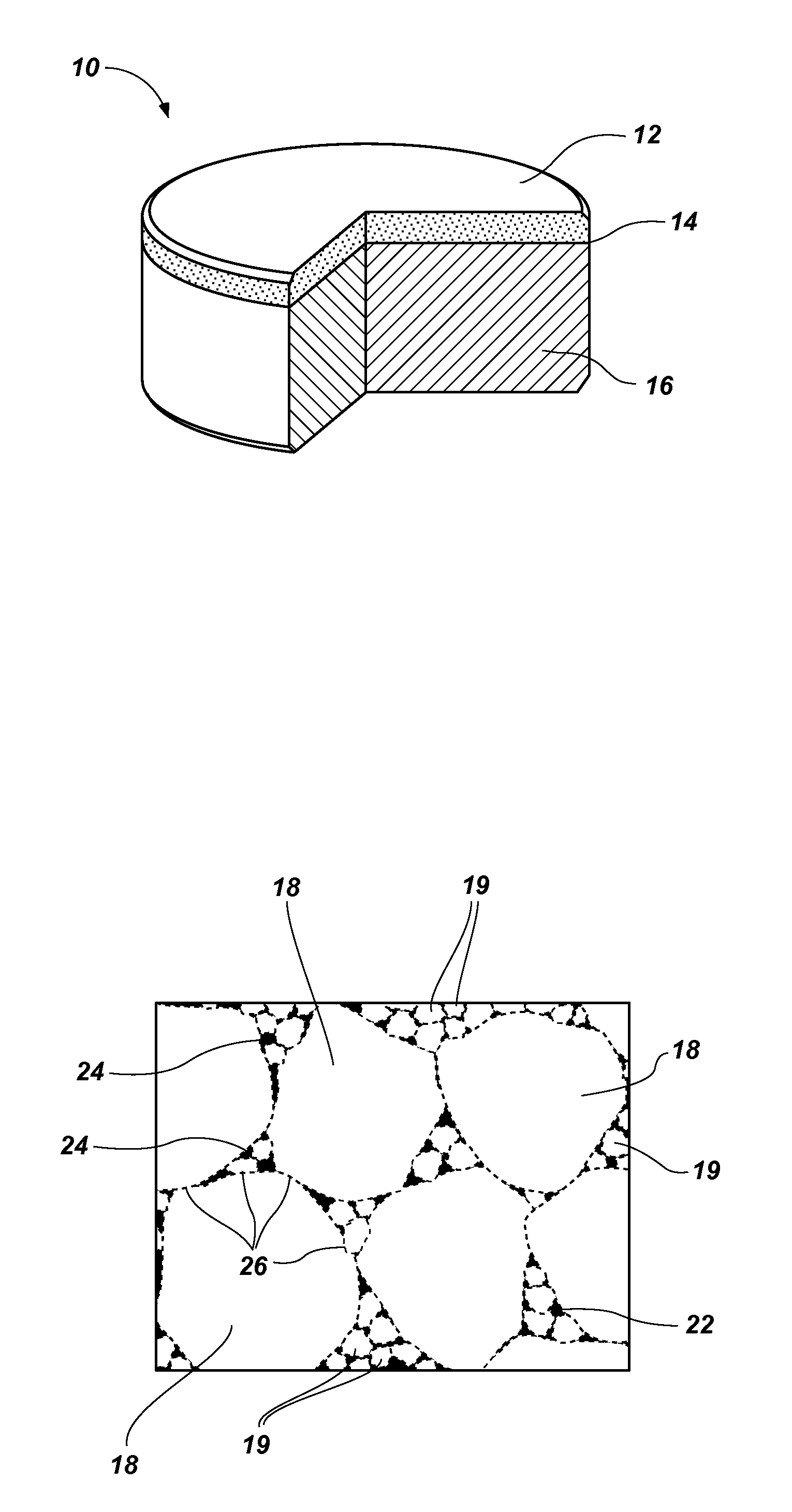
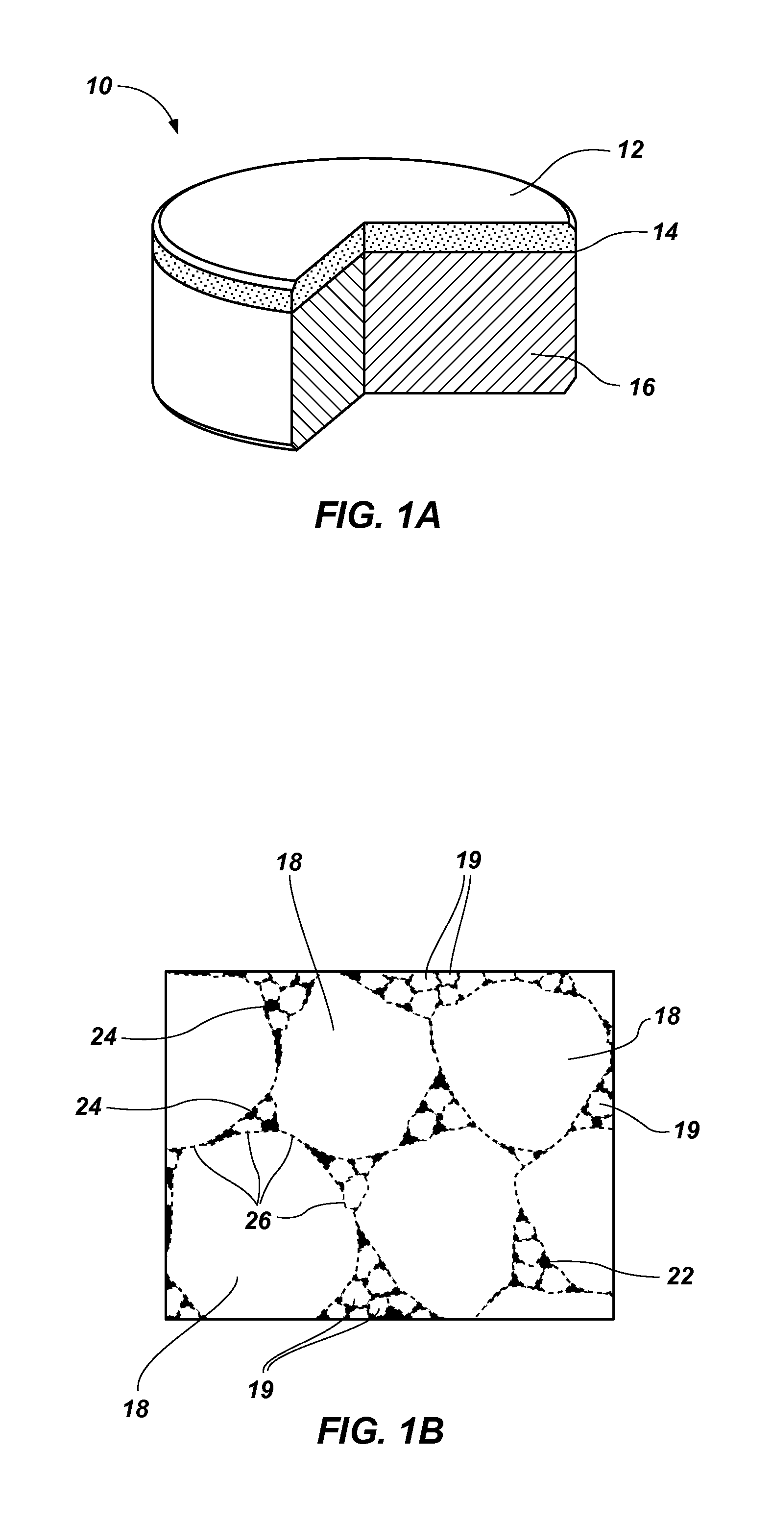
[0072] A polycrystalline compact, comprising: a plurality of grains of hard material, the plurality of grains of hard material being interbonded to form a polycrystalline hard material; and a plurality particles disposed in interstitial spaces between the grains of hard material, the plurality of particles comprising a non-catalytic, non-carbide-forming material.

[0073]Embodiment 2: The polycrystalline compact of Embodiment 1, wherein the plurality of grains of hard material comprises grains of diamond.

[0074]Embodiment 3: The polycrystalline compact of Embodiment 1 or Embodiment 2, wherein the particles comprise a refractory metal.

[0075]Embodiment 4: The polycrystalline compact of Embodiment 1 or Embodiment 2, wherein the particles comprise at least one of rhenium, osmium, ruthenium, rhodium, iridium, and platinum.

[0076]Embodiment 5: The polycrystalline compact of any one of Embodiments 1 through 4, further comprising a catalyst material in the interstitial spaces between the grains ...

embodiment 16

[0087] A method of forming a polycrystalline compact, comprising sintering a plurality of hard particles and a plurality particles to form a polycrystalline hard material comprising a plurality of interbonded grains of hard material, the particles comprising a non-catalytic, non-carbide-forming material.

[0088]Embodiment 17: The method of Embodiment 16, further comprising selecting each the hard particles of the plurality of hard particles to comprise diamond.

[0089]Embodiment 18: The method of Embodiment 16 or Embodiment 17, further comprising selecting the particles of the plurality of particles to a refractory metal.

[0090]Embodiment 19: The method of Embodiment 16 through 18, further comprising selecting the particles of the plurality of particles to comprise rhenium.

[0091]Embodiment 20: The method of any one of Embodiment 16 through 19, further comprising catalyzing the formation of inter-granular bonds between the grains of hard material.

[0092]Embodiment 21: The method of any one...

embodiment 23

[0094] A method of forming a cutting element, comprising infiltrating interstitial spaces between interbonded grains of hard material in a polycrystalline material with a plurality of particles, the particles comprising a non-catalytic, non-carbide-forming material.

[0095]Embodiment 24: The method of Embodiment 23, further comprising selecting the grains of hard material to comprise diamond grains.

[0096]Embodiment 25: The method of Embodiment 23 or Embodiment 24, further comprising selecting the particles of the plurality of particles to comprise a refractory metal.

[0097]Embodiment 26: The method of any one of Embodiments 23 through 25, further comprising selecting the particles of the plurality of particles to comprise at least one of rhenium, osmium, ruthenium, rhodium, iridium, platinum.


PUM

PropertyMeasurementUnit
temperatureaaaaaaaaaa
temperaturesaaaaaaaaaa

Abstract

Polycrystalline compacts include non-catalytic, non-carbide-forming particles in interstitial spaces between interbonded grains of hard material in a polycrystalline hard material. Cutting elements and earth-boring tools include such polycrystalline compacts. Methods of forming polycrystalline compacts include forming a polycrystalline material including a hard material and a plurality of particles comprising a non-catalytic, non-carbide-forming material. Methods of forming cutting elements include infiltrating interstitial spaces between interbonded grains of hard material in a polycrystalline material with a plurality of non-catalytic, non-carbide-forming particles.

Description

CROSS-REFERENCE TO RELATED APPLICATION[0001]This application claims the benefit of U.S. Provisional Patent Application Ser. No. 61 / 411,355, filed Nov. 8, 2010, entitled “Polycrystalline Compacts Including Nanoparticulate Inclusions, Cutting Elements and Earth-Boring Tools Including Such Compacts, and Methods of Forming Same,” the disclosure of which is incorporated herein by reference in its entirety.TECHNICAL FIELD[0002]The present disclosure relates generally to polycrystalline compacts, which may be used, for example, as cutting elements for earth-boring tools, and to methods of forming such polycrystalline compacts, cutting elements, and earth-boring tools.BACKGROUND[0003]Earth-boring tools for forming wellbores in subterranean earth formations generally include a plurality of cutting elements secured to a body. For example, fixed-cutter earth-boring rotary drill bits (also referred to as “drag bits”) include a plurality of cutting elements that are fixedly attached to a bit bod...

Claims


Application Information

Patent Timeline
Patent Type & Authority Applications(United States)
IPC IPC(8): E21B10/46E21B10/36B24D3/10B22F1/17
CPCE21B10/567E21B10/5735B24D3/10B24D99/005B22F3/14B22F7/08C22C26/00B22F2005/001B22F2998/10B22F1/17B22F3/26
Inventor DIGIOVANNI, ANTHONY A.
Owner BAKER HUGHES INC
Why Eureka
Try Eureka